


Answer:
The following options are available for modeling two welded members lying parallel to each other (Image 01):
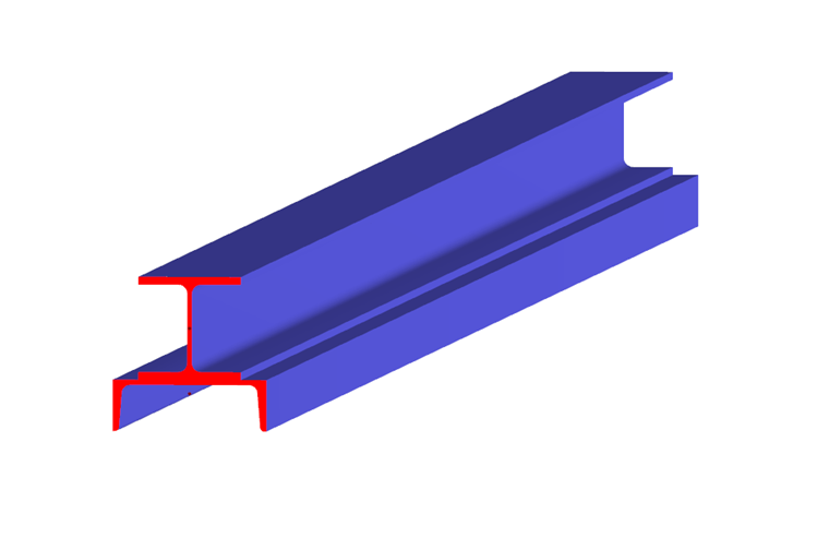
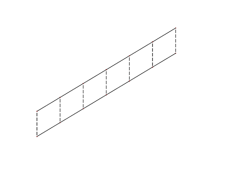
1) Connecting Both Members Using Rigid Members at Certain Distances
- Division of the members at certain distances: Right-click the corresponding members → "Divide Member"
- Connection of the newly created nodes using rigid members
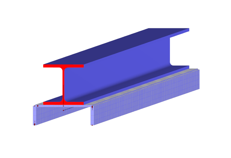
2) Generating Surface from Member (possible in RFEM only)
- Right-click one of the members → "Generate Surfaces from Member"
- Displacement of the other member into a plane of the newly created surfaces in a way so that the line of the displaced member is integrated into the corresponding surface (check: dialog box "Edit Surface" → tab "Integrated")
- Defining a member eccentricity in a way so that the original position is restored ("Edit Member" → "Settings" tab → "New Member Eccentricity" → here practically: "Relative Offset")
- If the member used for generating surfaces is designed in an add-on module, you can simply define a result member here.
3) Using SHAPE-THIN
Use the SHAPE-THIN stand-alone program to model and design the individual cross-sections.