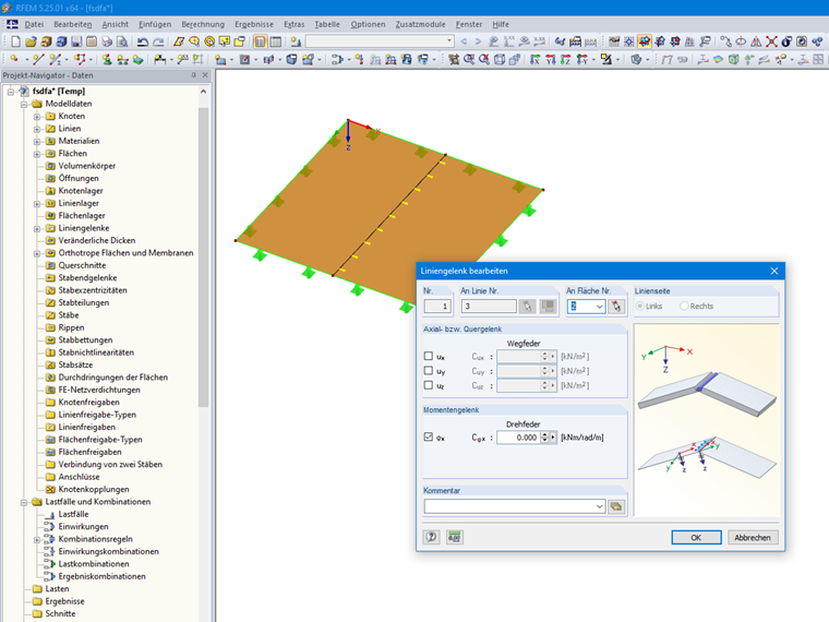
Axial / Shear Hinge or Spring
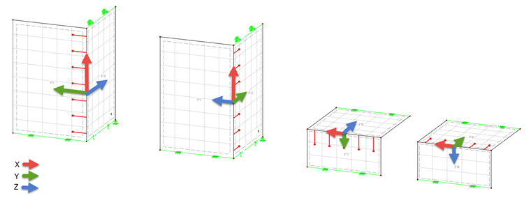
The degrees of freedom are based on the following definition of the axis system:
The x-axis points in the direction of the line, the y-axis represents the tangent to the surface plane, the z-axis is the normal to the surface.
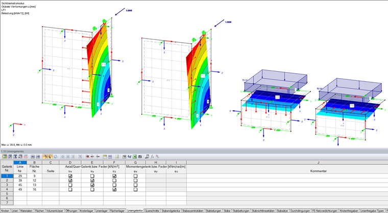
The text boxes and table columns control the degrees of freedom for axial and shear forces. If a check box is selected, it means that the displacement in this direction is possible and thus the force is not transferred. It is also possible to enter the constant of a translational spring.
Moment Hinge or Spring
The degrees of freedom for the moments refer to the local axis system of the hinge (axis x in the direction of the line, axis y as the tangent, and axis z as the normal to the surface plane). A check mark indicates that the rotation is free and the internal force is not transferred. It is also possible to enter the constant of a rotational spring.
Evaluation of Release Results
The results of the line hinges also refer to the internal line hinge coordinate system (axis x in the direction of the line, axis y as the tangent, and axis z as the normal to the surface plane).
| DOF | Description |
|---|---|
| n | Shear flow along the line |
| vz | Shear force parallel to the surface axis z |
| vy | Shear force tangential to the surface plane |
The coordinate system is shown in Image 03.