The structural analysis software RFEM 6 is the basis of a modular software system. The main program RFEM 6 is used to define structures, materials, and loads of planar and spatial structural systems consisting of plates, walls, shells, and members. The program also allows you to create combined structures as well as to model solid and contact elements.
RSTAB 9 is a powerful analysis and design software for 3D beam, frame, or truss structure calculations, reflecting the current state of the art and helping structural engineers meet requirements in modern civil engineering.
Do you often spend too long calculating cross-sections? Dlubal Software and the RSECTION stand-alone program facilitate your work by determining section properties of various cross-sections and performing a subsequent stress analysis.
Do you always know where the wind is blowing from? From the direction of innovation, of course! With RWIND 2, you have a program at your side that uses a digital wind tunnel for the numerical simulation of wind flows. The program simulates these flows around any building geometry and determines the wind loads on the surfaces.
Are you looking for an overview of snow load zones, wind zones, and seismic zones? Then you are in the right place. Use the Geo-Zone Tool to determine quickly and efficiently snow loads, wind speeds, and seismic data according to ASCE 7‑16 and other international standards.
Would you like to try out the capabilities of the Dlubal Software programs? You have the opportunity to do so! The free 90-day full version allows you to thoroughly test all our programs.
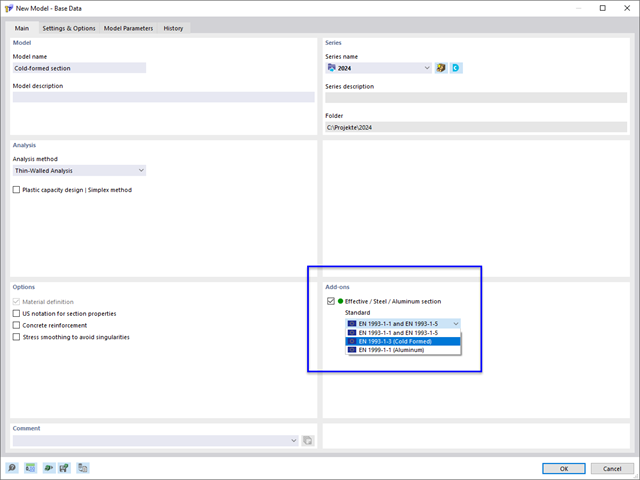
In the RSECTION program, you can analyze general steel or aluminum cross-sections and determine the effective section properties. For this, you need the Effective Sections program extension of RSECTION. If you have licensed this add-on, you can activate the Effective Section option for the calculation in the Base Data of the cross-section.
Then, define the standard according to which the calculation should be performed. Currently, the following options are available:
The effective section properties depend on the internal forces of the cross-section. Therefore, create a load case and define one or more internal force constellations.
After the calculation, the effective section properties are displayed in the table. In the graphic, you can check the stresses on the effective section.
Once you have saved the cross-section, you can import it into RFEM or RSTAB to use it for further analyses.
The webinar Determination of Section Properties and Stress Analysis in RSECTION shows the modeling and calculation of a cold-formed section. You can find further information there.
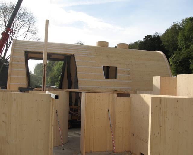
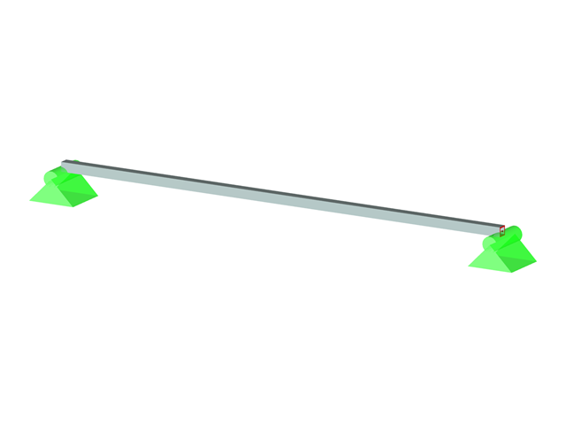
RFEM allows you to perform structural analysis and design of laminate and sandwich structures. The same applies to the cross-laminated timber. Stress and deflection analysis of laminate and sandwich surfaces is performed according to the laminate theory, taking into account the shear coupling.
Programs and Add-ons
RFEM is the main program that you can use to define the model and actions. You can model planar and spatial structures, consisting of plates, walls, shells, and members.
For the stress and deflection analysis, you need the Multilayer Surfaces add-on. It allows you to define and analyze layer structures.
Use the Timber Design add-on to also design the member supporting elements of the structure according to Eurocode 5 or ANSI/AWC NDS, for example.
Dynamic Analysis
If you need to perform a seismic or vibration analysis, the corresponding Dynamic Analysis add-ons are the perfect tools for determining natural frequencies and mode shapes, or for the analysis of external excitations.
In case of any questions about the Dlubal timber design solutions, our sales team will be happy to assist you.
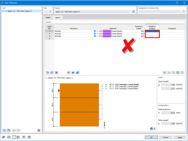
If no angle can be defined in the "Rotation" column, there is an isotropic material model selected for the material, where stiffnesses are identical in all directions and it is not necessary to define an angle.
If you use materials with anisotropic behavior (for example, timber), it is necessary to ensure that the "Orthotropic | Linear Elastic (Surfaces)" material model is selected.
Note: The "Orthotropic | Timber | Linear Elastic (Surfaces)" material model cannot be currently used in combination with the "Layers" thickness type.
As soon as switching to the orthotropic material model, the individual layers can be rotated accordingly.
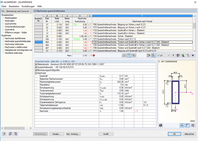
If there are member sections connected by welds, you can define the arrangement and design of the transverse welds in Window 1.5. This allows you to determine the cross-section softening in the heat affected zone.
According to EN 1999‑1‑1, Clause 6.1.6.2, NOTE 2, there are two options to consider the reduced strength:In the case of the reduced stress method, the strength values f,o,haz and fu,haz are reduced in accordance with Table 3.2. On the other hand, the effective cross-section method uses the reduced cross-section properties for the design (area A, section moduli W, moments of inertia I).
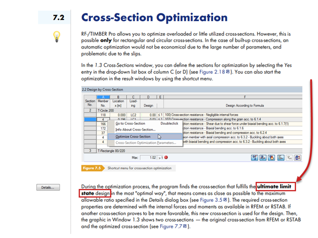
The optimization of cross-sections in RF‑/TIMBER Pro is based exclusively on the ultimate limit state (ULS), not the serviceability limit state (SLS); see the image from the RF‑TIMBER Pro manual.
More information about the cross-section optimization can be found in the RF-TIMBER Pro manual on pages 76-78 (also available using the F1 key in the add-on module).
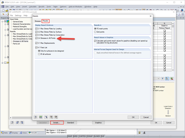
In the graphic, this is not possible for reasons of clarity. However, the RF‑LAMINATE add-on module also allows you to display the stresses in all points. This is deactivated by default because it quickly produces a huge amount of data for large structures.
If you also filter by the stress component that interests you, the results in the table quickly become clear, and you can easily evaluate the distribution of stresses at a point using the layers there.
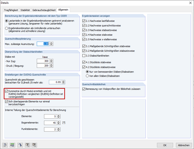
RF‑/ALUMINUM checks the symmetry of general cross-sections and compares them with the SHAPE‑THIN evaluation when activating the "Determine symmetry by module and compare with SHAPE‑THIN definition" check box (Image 01).
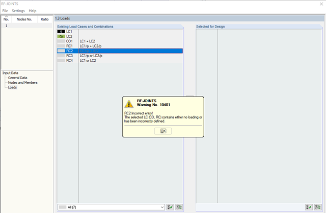
If the two methods provide different results, the corresponding error message appears (Image 02).
Usually, there are small inaccuracies in the SHAPE‑THIN cross-section. Thus, the cross-section Sec‑1.du9 shown in Image 03 is not absolutely symmetrical to the Z‑axis: The Z‑coordinates of Node 1 and Node 4 as well as Node 55 and Node 60 do not match in the second decimal place.
SHAPE‑THIN classifies the cross-section as asymmetrical, but RF‑/ALUMINUM as monosymmetric to the z‑axis, so the error message shown in Image 02 appears.
The SHAPE‑THIN cross-section should be checked for symmetry. When modeling in SHAPE‑THIN, it is useful to display only one side of the cross-section and create the other half by mirroring. This is also shown in the video.
Yes, the materials are freely available. With the following download option, you can get the presentations and finished models of the speakers.
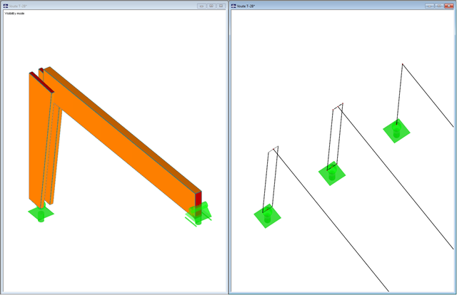
In the RF‑/TIMBER Pro add-on module, you can design double rectangular cross-sections ("H‑2B" cross-section) with a constant cross-section height over the member length. Tapered H‑2B cross-sections are excluded from the design.
In this case, it is useful to display the H‑2B cross-section using two separate rectangular cross-sections. You can either model both members geometrically separately and couple them, for example, with rigid members, or activate the "Allow double members" option in the "Edit" menu and assign the corresponding eccentricities to the two members, which are initially on top of each other. These members can then be designed in RF‑/TIMBER Pro.
Under "Downloads" below, you can find an example file.