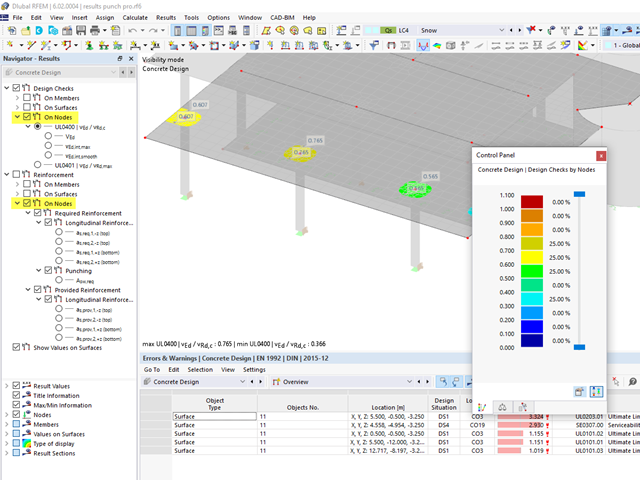
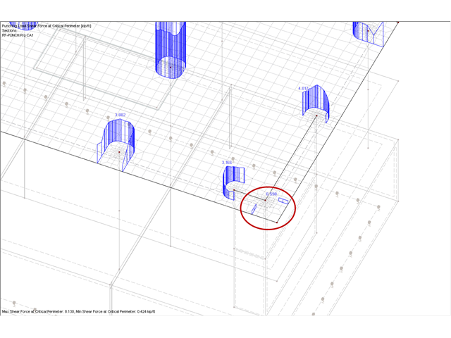
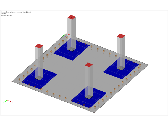
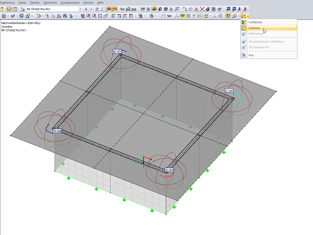
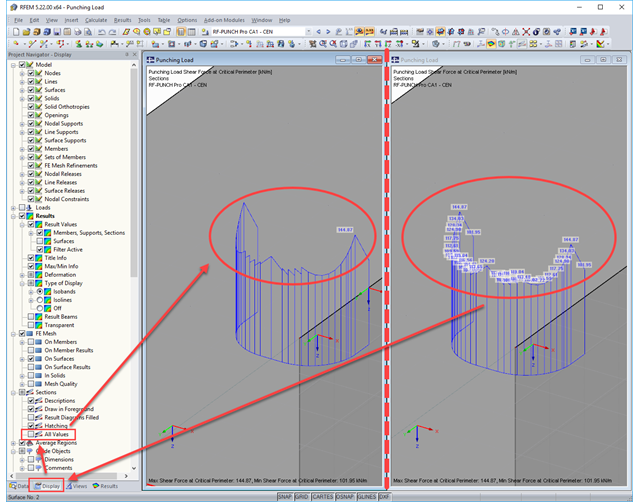
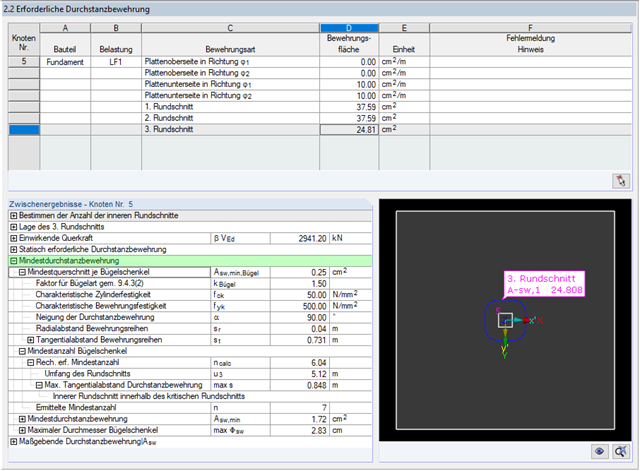
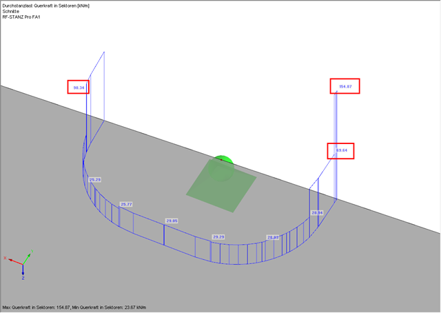
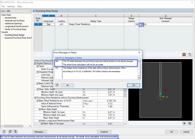
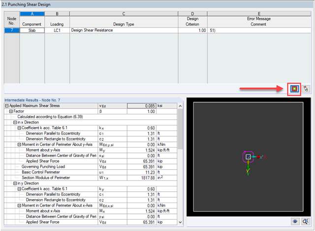
Where can I find the graphical results of punching shear in the concrete design? Especially the distribution of shear forces at the critical perimeter or the punching loads.
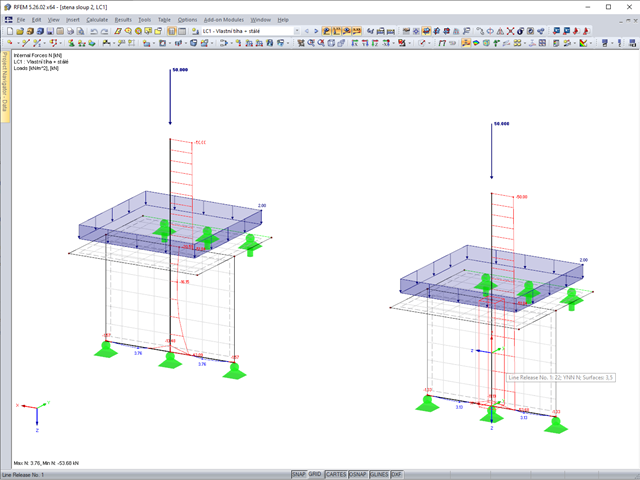
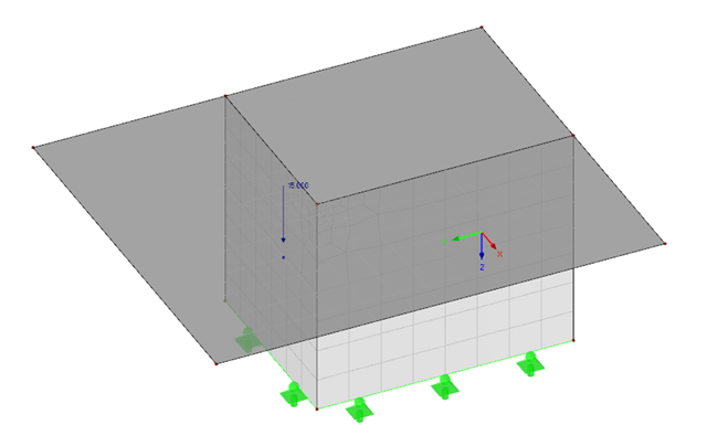
I have a roof structure resting on a steel column that runs to the foundations. The column runs through a perimeter wall that supports the false ceiling. A considerable part of the load from the roof is transferred to the wall. I want the steel column to carry all the vertical loads from the roof. How can I do it?
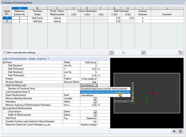
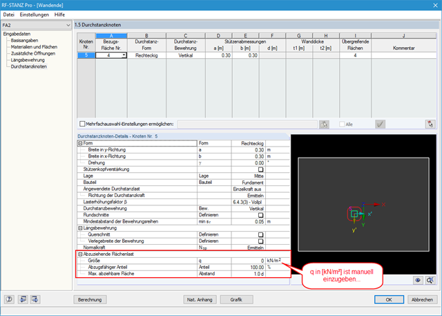
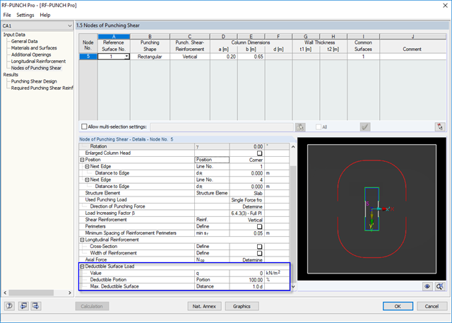
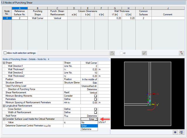
Why is it not possible to specify a "favorably acting soil contact stress" at a wall corner or wall end for punching shear design of a floor slab? Where can I find the input option for this?
For wall ends and wall corners, no soil contact stresses are deducted in RF‑PUNCH Pro, even though the "Foundation" type has been set. Furthermore, there seems to be no option anywhere to set the soil contact stresses to be deducted. Why?
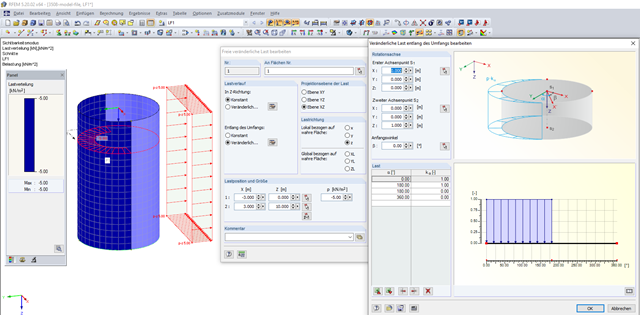
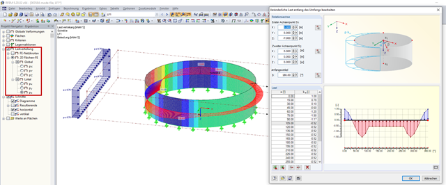
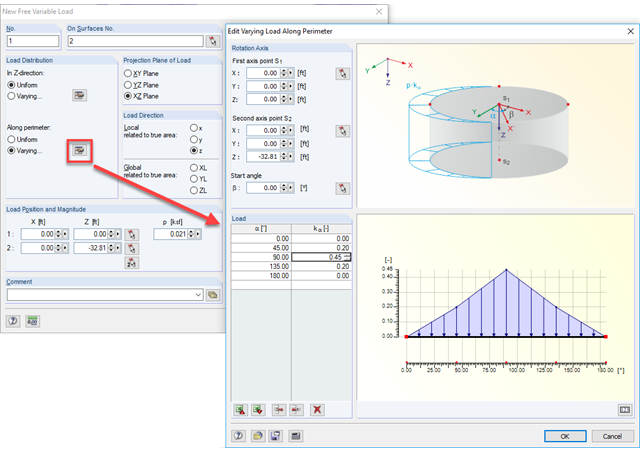
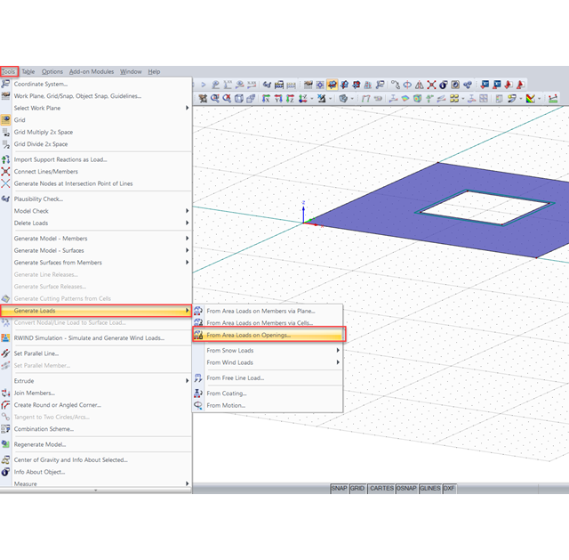
When I apply an area load to a surface with an opening, the load is not not accounted for at the opening. Is it possible to automatically consider the area load as a line load around the opening perimeter?
In some areas of the modeled downstand beams or ribs, there are also walls or pilasters. Is it necessary to separate and remove the downstand beams on the walls, or should they continue through them?
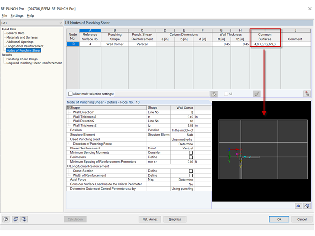
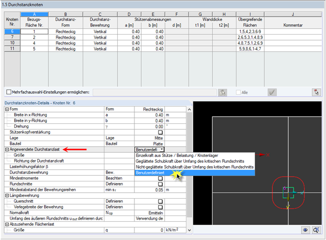
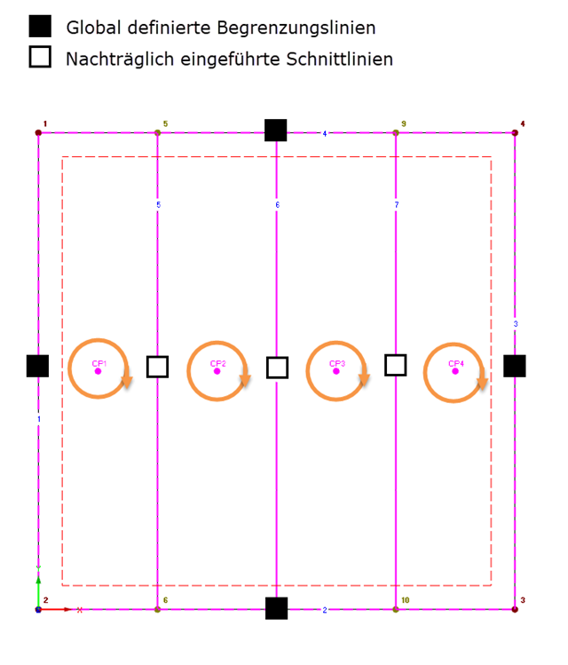
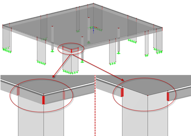
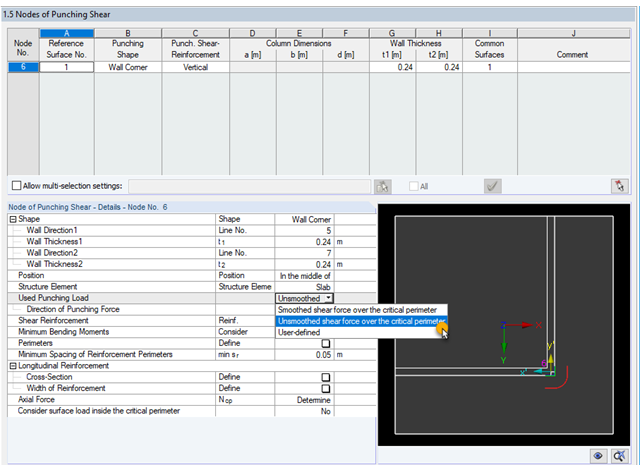
Is the punching load in RF‑PUNCH Pro taken from the support forces of line supports in the case of the design on a wall corner? Which lengths are decisive for applying the support forces?
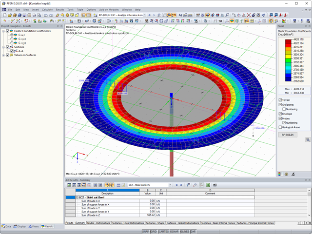
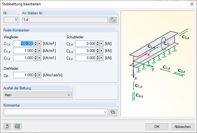
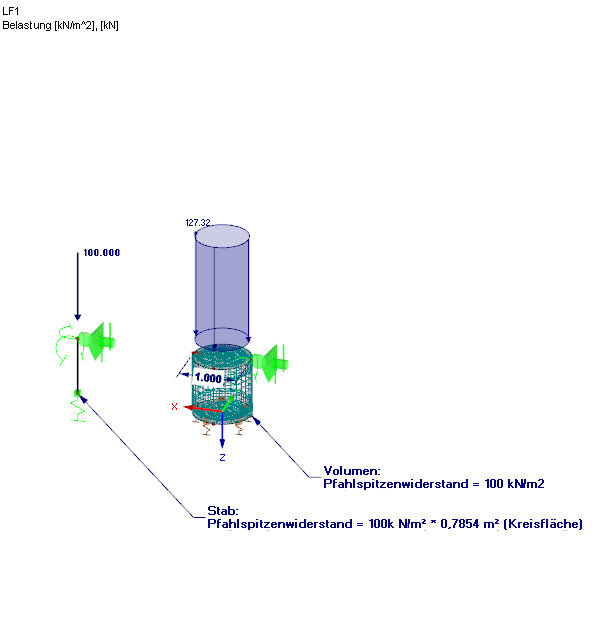
How is it possible to enter the values for skin friction and pile end resistance when displaying bored piles for the design of member elastic foundations in the program?