


Plastic deformations represent material properties that require a nonlinear analysis. Utilize RFEM together with the RF-MAT NL add-on module to consider elastic-plastic material behavior in the analysis.
In addition to the yield condition according to von Mises, the approaches according to Tresca, Drucker-Prager, and Mohr-Coulomb are available as strain hypotheses. For ductile materials such as steel, we recommend the plasticity theory according to von Mises. For the general spatial stress state, it is as follows:
Read more about the stress hypotheses here:
Using a simple model with uniaxial loading, the possibilities of plastic analyses with RFEM and RF-MAT NL are presented.
Tensile Test Specimen Example
A tensile test specimen made of S 235 steel with the dimensions shown in Image 01 is restrained at one end. The model is created as a surface with 2D elements.
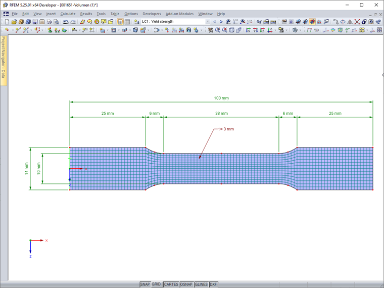
Due to the very small dimensions of the test specimen, an FE mesh size of 1 mm is selected. Only the stresses due to tensile stress according to the linear static analysis are to be analyzed; a stability analysis is not performed.
Tensile Stress up to Yield Strength
The force required to reach the yield strength is determined for the model as follows:
N = fy · A = 235 N/mm² · (10 mm · 3 mm) = 7,050 N
It is applied as a line load at the end of the test specimen:
7,050 N/14 mm = 503.57 N/mm = 503.57 kN/m
Load Case 1 is first calculated with the standard isotropic linear-elastic material model according to the linear static analysis. The self-weight is not taken into account.
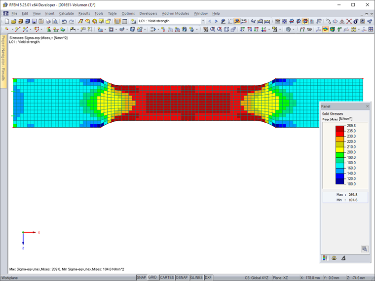
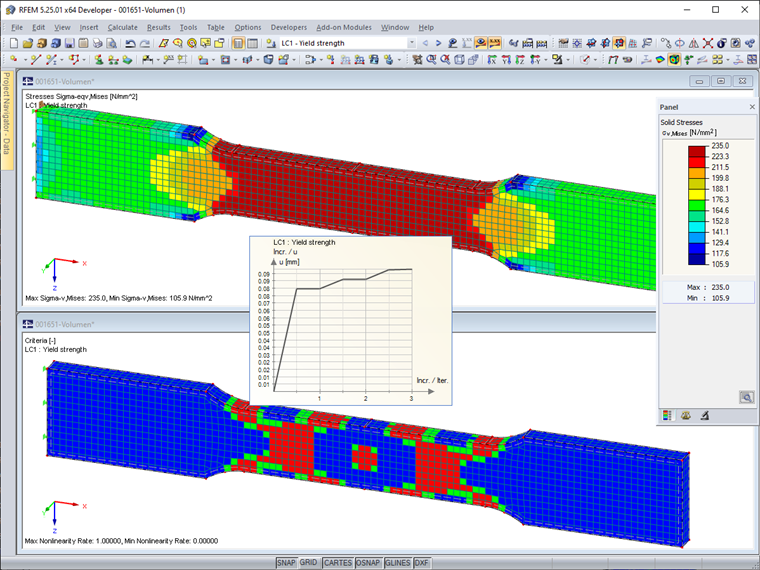
To display the equivalent stresses according to von Mises, the "Constant on Elements" result diagram is selected. Thus, there is no smoothing across the element boundaries. Image 02 shows that the yield stress of 235 N/mm² is exceeded in areas of the reduced cross-section. Therefore, the results do not reflect the stress distribution of a tensile test with yield effects.
For a realistic calculation, we recommend using the "Isotropic Plastic 2D/3D" material model, which is available with an RF-MAT NL license. This material model shows an isotropic material behavior in the elastic zone. The plastic area is based on the yield conditions of the von Mises strain hypothesis with a yield strength of the equivalent stress of 235 N/mm². The calculation is performed iteratively in several load steps. For this, the "Number of load increments for Newton-Raphson method to determine automatically" option is used, which can be activated in the RFEM calculation parameters for materials with a nonlinear model. This ensures the required accuracy of the results with a relatively short calculation time.
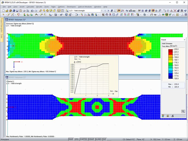
Image 03 shows the stresses and the degree of nonlinearity (proportion of elements with yields) of the nonlinear material model. The yield strength of 235 N/mm² is not exceeded in any element. The calculation diagram shows the deformation diagram during the iterations.
Load Increment and Yielding
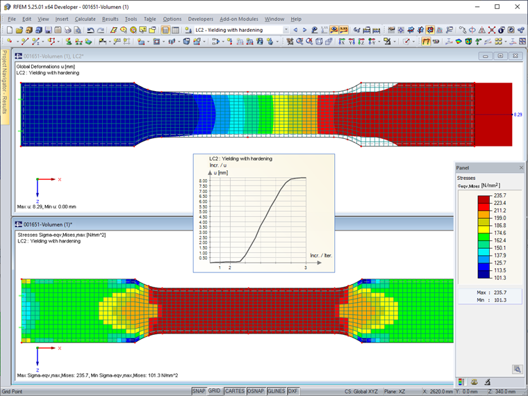
In LC 2, the "yield load" is increased slightly from 503.57 kN/m to 505.00 kN/m. The calculation provides a strong total strain of the test specimen of 8.29 mm (for comparison: 0.10 mm in LC 1). However, there is still a convergence, which is not least due to the strain hardening modulus Ep = 2.1 N/mm² (see the technical article
KB001479 | Hardening Parameters in Nonlinear Material Models
). The weakened area of the cross-section is completely in the yield state.
In the elastic-plastic calculation, the total strain ε is divided into an elastic component εel and a plastic component εpl.
ε = εel + εpl
However, this breakdown is only valid when assuming that the plastic strains are small. Here, εpl < 0.1 can be assumed as a rule of thumb (see the COMSOL® Learning Center). If the plastic strains are too large, the plastic results should be evaluated with caution.
The axial strain in the tapered area (assumption: l = 38 mm) due to elastic strain is:
εel = σ / E = 235 N/mm² / 210,000 N/mm² = 0.00119
∆lel = 0.00119 · 38 mm = 0.04 mm
This deformation can also be checked in Table "4.2 Nodes – Deformations" from the difference of the displacements uX of Nodes 4 and 5 in LC 1.
In LC 2, the displacements of these nodes result in the following plastic strain:
εpl = (∆ltot - ∆lel ) / l = (8.24 mm - 0.05 mm - 0.04 mm) / 38 mm = 0.21 > 0.1
Thus, the limits of the nonlinear material model are exceeded. For comparison, further analyses are carried out on a 3D model of the tensile test specimen, which records the spatial component in a solid model.
Solid Model
The 3D model is also meshed with a mesh size of 1 mm. This results in three finite solid elements over the cross-section thickness.
The force of 7,050 N required to reach the yield strength (see above) is applied as a surface load at the end of the test specimen. It is determined as follows:
7,050 N / (14 mm · 3 mm) = 167.857 N/mm² = 167,857 kN/m²
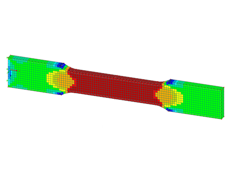
As shown in Image 05, the equivalent solid stresses and the nonlinearity ratio of LC 1 confirm the results of the surface model.
The calculation of LC 2—with an equivalent surface load of 168,333 kN/m²—results in a smaller total deformation of 0.22 mm in the solid model than in the surface model with 8.29 mm. In the calculation diagram, however, the nonlinear effects of the material flow are also clearly visible.
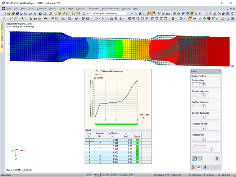
As shown in Image 06, the deformation figure (in an exaggerated representation) reflects the start of the constriction, including transverse deformation.
The solid model is, therefore, an interesting alternative for representing the yielding process. Only a load of about 177,900 kN/m² would lead to a deformation of 8.29 mm of LC 2 in the surface model. This corresponds to an increase of the yield strength load by 6% (surface model: 0.3%).
The comparison of the model with the real material behavior can ultimately be carried out by a corresponding experimental arrangement with a tensile test.
Summary
Using a simple example, we showed how nonlinear material laws can be represented and analyzed in RFEM. Both surface and solid elements can be modeled. The solid model is generally recommended if the influence of the element thickness is relevant. For relatively slender objects, however, the surface model is the first choice; it also requires less modeling and calculation effort.
Plastic material properties, such as flow behavior, can be displayed using the RF-MAT NL add-on module. In such a case, user-defined stress-strain diagrams based on empirically determined data are also possible. In the presented example, the standard diagram with a preset strain hardening factor was used.
With the help of nonlinear material models, it is also possible to determine redistribution effects in the model that result, for example, from the formation of plastic hinges. For plastic effects, results with large deformations—especially according to the large deformation analysis—have to be evaluated with caution.
Find more explanations and examples in our Knowledge Base articles and FAQ, which are linked below this article.