


Input for determining flange widths of rib members using formulas of Eurocode 2
Reference to Eurocode 2
According to [1], 5.3.2.1(2), the effective slab width is normally to be determined on the basis of the distance l0 available between the zero moment points. This means that the segment lengths should be oriented to the system's points of zero moments.
For a single-span beam with pinned supports, input is rather easy because the member length is equal to the segment length.
Two-Span Beam Example
In this example, input for a two-span beam is described, for which the entries regarding the reference length l0 from [1], Figure 5.2 are specified in the "Edit Member" dialog box of the rib member.
According to Figure 5.2 from [1], the following reference lengths l0 result for the individual spans li of a continuous beam, which are designated as lref in the user interface:
![Spans Based on Figure 5.2 from [1]](/en/webimage/039540/3493372/01_Abmessungen_EN.png?mw=760&hash=8754daf9cdfcd67171af683c3ab3b9708f2cd3ef)
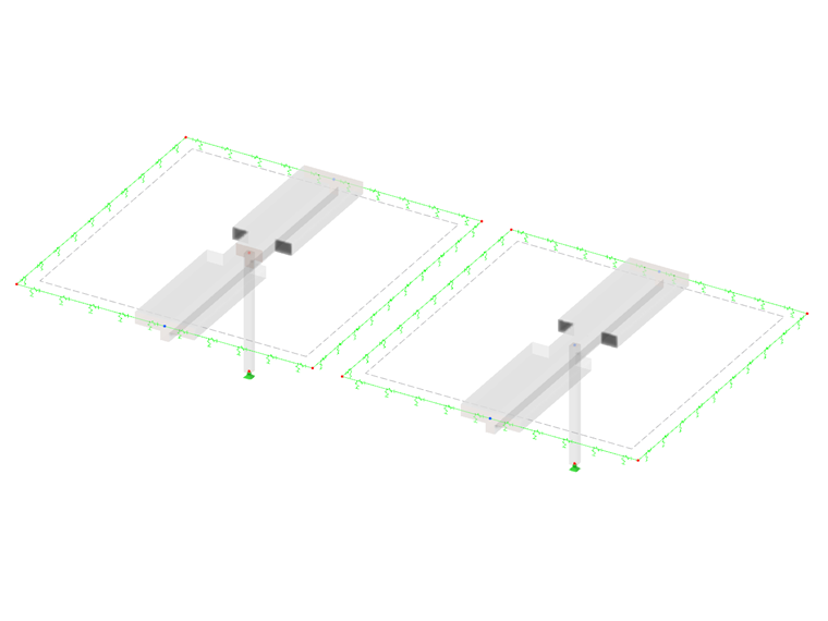
This article describes the input for a two-span rib member. Its dimensions in the RFEM model are as follows:

Two different input methods are described below.
- Model consisting of two rib members
- Model with continuous member and nodes of "On Line" type
Model Consisting of Two Rib Members
In this system, we need to implement the specifications regarding the reference lengths by means of the edge span l1 from [1], Figure 5.2. This means that the first "segment" has a reference length of 85% of the member length of the first span. Accordingly, when entering the rib member, the first segment length is defined in the "Rib" tab as follows:
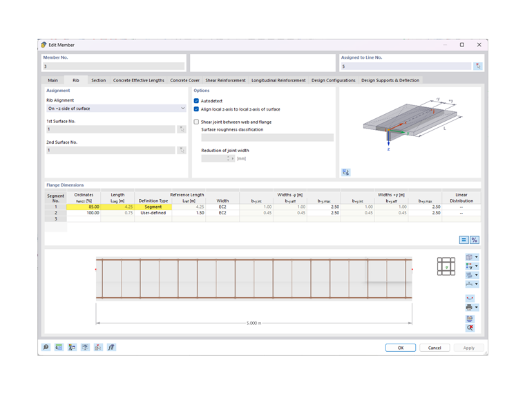
Determining the second segment length l0 above the column requires the lengths l1 and l2 of both spans adjacent to the column (see Figure 5.2 in [1]). However, RFEM 6 cannot determine it automatically with this type of input (standard node above column). This means for entering data in RFEM that the "Definition Type" for the second segment must be changed to "User-defined" and the segment length must be entered manually. In this example, the resulting length to be entered is l0 = 0.15*(5.00 m + 5.00 m) = 1.50 m.
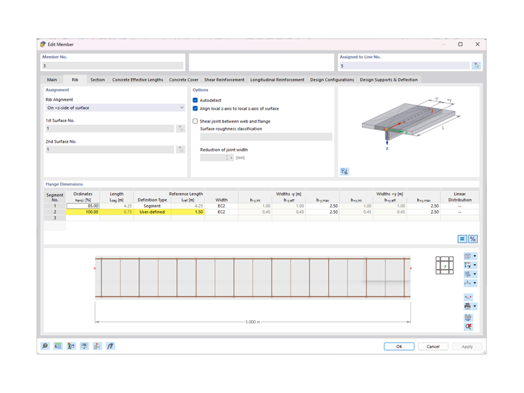
It is now necessary to repeat the entries for the first member of the two-span rib member for the second member. Here it is important, however, to ensure that the entries of the segments are reversed accordingly, and that in this case the user-defined segment including lref = 1.50 m has to be entered before the segment including lref = 4.25 m.
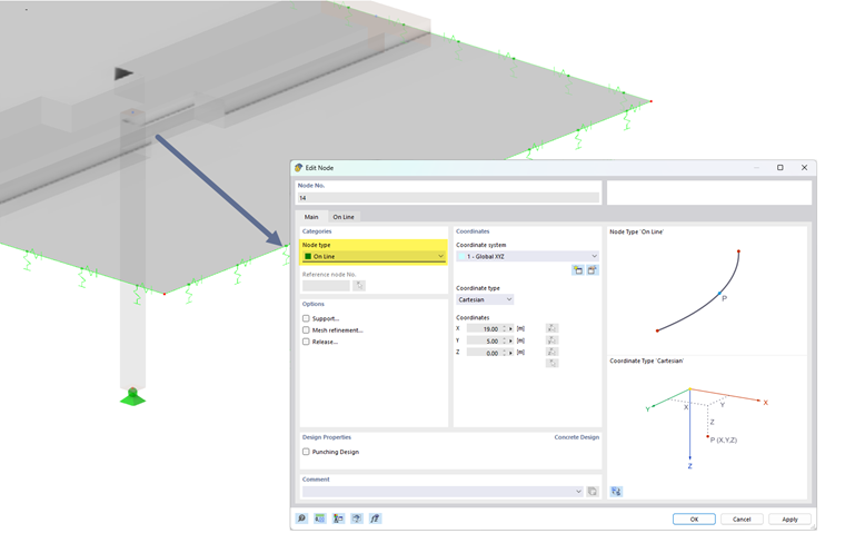
Model with Continuous Member and Nodes of "On Line" Type
As you can see in the description above, defining the segment lengths to determine the flange widths is relatively complex for a two-span beam consisting of two single members.
Therefore, an option was implemented in RFEM 6 to enter a two- or multi-span beam consisting of one member. In this case, a node of the "On Line" type is entered at the point where the column is to be connected to the beam so that the beam no longer needs to be divided into individual members.
Since you only have to edit one member for the beam with this input method, you can now define all segments for determining the rib widths more easily.
In this case, it is sufficient to specify the length of the respective segment in the first column called "Ordinates". By default, it is done by entering a percentage. For this two-span beam, crossing the zero moments can be assumed and entered at 42.5% or 57.5% of the member length, based on [1], Figure 5.2.
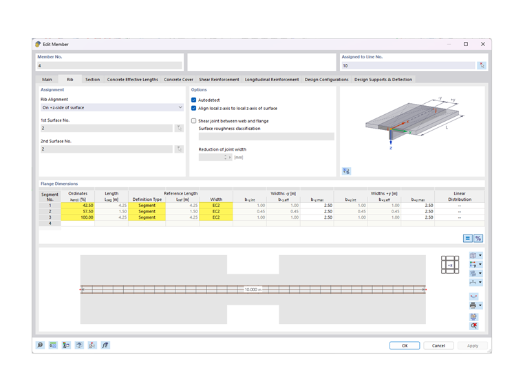
In this case, the percentage values result from the analysis of a two-span beam. For continuous beams with a different number of spans, you must adjust these percentage values accordingly.
Comparison of both Input Methods
Depending on how the model was entered or generated using BIM interfaces, both input methods can be considered. The first option, of defining the continuous beam by means of individual members, corresponds more to the classic input known from RFEM 5. However, the definition of segment lengths, as described in this example, is a bit more complex here. Therefore, if possible, we recommend entering the ribs as continuous beams using nodes of the "On Line" type. On one hand, it simplifies the input of the ribs' segment lengths; on the other hand, it is possible to define the reinforcement for the downstand or T-beam on one member. Entering a member set for a uniform definition of the reinforcement would also be omitted in this case.
The effective widths of the ribs, however, are identical.
Limitation of Widths b-y,max and b+y,max
If several downstand beams are entered parallel to each other in a ribbed slab, the calculated value of the flange width of the individual rib members might "overlap". In order to prevent this overlap, you can define the limit values b-y,max and b+y,max according to [1] Figure 5.3 and the widths bi. In the present example—see the images above—this was input as 2.50 m.
