95 Results
View Results:
Sort by:

- 000487
- Modeling | Structure
- RFEM 5
-
- RF-STEEL 5
- RF-STEEL AISC 5
- RF-STEEL AS 5
- RF-STEEL BS 5
- RF-STEEL CSA 5
- RF-STEEL EC3 5
- RF-STEEL GB 5
- RF-STEEL HK 5
- RF-STEEL IS 5
- RF-STEEL NBR 5
- RF-STEEL NTC-DF 5
- RF-STEEL SANS 5
- RF-STEEL SIA 5
- RF-STEEL SP 5
- RF-ALUMINUM 5
- RF-ALUMINUM ADM 5
- RSTAB 8
- STEEL 8
- STEEL AISC 8
- STEEL AS 8
- STEEL BS 8
- STEEL CSA 8
- STEEL EC3 8
- STEEL GB 8
- STEEL HK 8
- STEEL IS 8
- STEEL NBR 8
- STEEL NTC-DF 8
- STEEL SANS 8
- STEEL SIA 8
- STEEL SP 8
- ALUMINUM 8
- ALUMINUM ADM 8
- Steel Structures
- Process Manufacturing Plants
- Stairway Structures
- Structural Analysis & Design
- Eurocode 3
- ANSI/AISC 360
- SIA 263
- IS 800
- BS 5950-1
- GB 50017
- CSA S16
- AS 4100
- SP 16.13330
- SANS 10162-1
- ABNT NBR 800
- ADM
The support conditions of a beam subjected to bending are essential for its resistance to lateral-torsional buckling. If, for example, a single-span beam is held laterally in the middle of the span, the deflection of the compressed flange can be prevented, and a two-wave eigenmode can be enforced. The critical lateral-torsional buckling moment is increased significantly by this additional measure. In the add-on modules for member design, different types of lateral supports on a member can be defined using the "Intermediate supports" input window.

When optimizing cross-sections in the add-on modules, you can also select arbitrarily defined cross-section favorites lists - in addition to the cross-sections from the same cross-section series as the original cross-section.

In the case of open cross-sections, the torsional load is removed mainly via secondary torsion, since the St. Venant torsional stiffness is low compared to the warping stiffness. Therefore, warping stiffeners in the cross-section are particularly interesting for the lateral-torsional buckling analysis, as they can significantly reduce the rotation. For this, end plates or welded stiffeners and sections are suitable.

The Eurocode for DIN EN 1991‑1‑4:2010‑12 describes wind loads acting on structural systems.

For automatic load case combination in RFEM and RSTAB, you have to enter the possible interaction of load cases. In addition to the simultaneous or alternative occurrence of all load cases of an action, an option for different combination conditions is possible.

In RFEM and RSTAB, snow drift is considered according to 5.3.4(3) of DIN EN 1991‑1‑3 for saw-tooth roofs.

The automatic creation of combinations in RFEM and RSTAB with the "EN 1990 + EN 1991‑3; Cranes" option allows you to design crane runway beams as well as support loads on the rest of the structure.
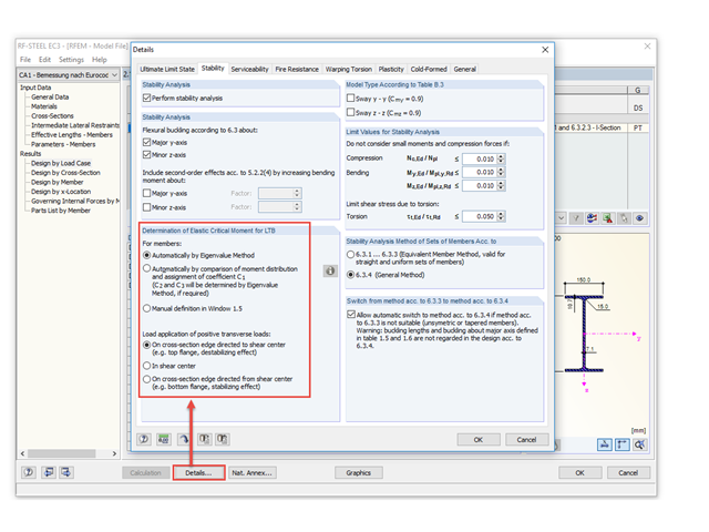
Occasionally, the question arises how to determine the correct load application point of the positive transverse loads in RF-/STEEL EC3 and RF-/STEEL AISC.

In addition to the geometry and shape of a flat roof, you can also take into account the formation of an eaves area when generating the loading.
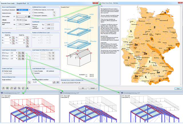
Eurocode 1, Parts 1 to 3, and American standard ASCE/SEI 7-16 describe the general effects due to snow loads. The load applications for duopitch, monopitch, and flat roofs required by the standards are stored in a tool in RFEM and RSTAB so that these effects can be generated easily.

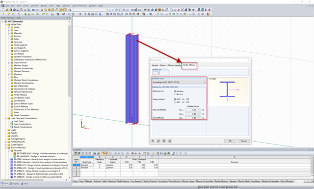
With RFEM version 5.06, member stiffnesses can be influenced by methods that are aligned with US steel construction standard ANSI/AISC 360-10. According to this standard, reduction factor τb must be considered for the determination of internal forces in all members of which the flexural resistance contributes to the model's stability. This coefficient depends on the axial force in the member: The larger the axial force, the larger τb is.
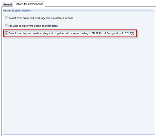
In the H - Roofs category, imposed loads have to be applied. These are usually the technician loads for construction and maintenance. Since there is no maintenance for snow, category H must not include both snow and imposed loads together. You can consider thi in the options for automatic combinations.
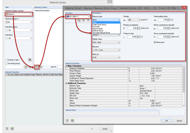
At first glance, the material list for masonry seems empty. The reason for this is that bricks and mortar can be used in many combinations, which would lead to a very long and unclear list. Therefore, it is necessary first to create a new material for masonry in order to consider these possible combinations in the calculation.
Requirements for the design of structural stability are given in the AISC 360 – 14th Ed. Chapter C. In particular, the direct analysis method provisions, previously located in Appendix 7 of the AISC 360 – 13th Ed., are described in detail. This method is considered an alternative to the effective length method, which in turn eliminates the need for effective length (K) factors other than 1.0.
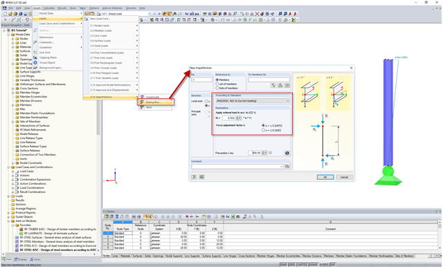
In the AISC 360 – 14th Ed. C2.2, the direct analysis method requires initial imperfections to be taken into consideration. The important imperfection of recognition is column out-of-plumbness. According to C2.2a, the direct modeling of imperfections is one method to account for the effect of initial imperfections. However, in many situations, the expected displacements may not be known or easily predicted.
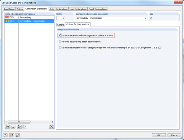
According to DIN EN 1990/NA:2010‑12 – NDP to A.1.2.1(1) Comment 2, it is necessary to apply only one of the two climatic actions in the combination expressions for actions according to 6.4.3 and 6.5.3 in the case of places located up to +1,000 m above mean sea level if snow and wind are available as collateral actions, in addition to non‑climatic leading action.
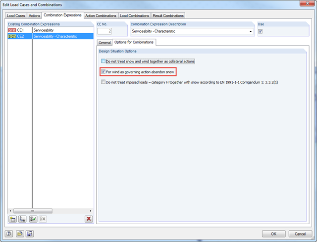
According to DIN EN 1990/NA:2010‑12 - NDP to A.1.2.1(1) Comment 2, it is possible to neglect the combination of snow as a collateral action in cases of wind/snow combination with wind as the leading action in wind zones III and IV.
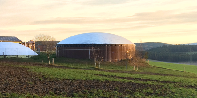
Due to the structural efficiency and economic benefits, dome-shaped roofs are frequently used for storehouses or stadiums. Even if the dome has the corresponding geometrical shape, it is not easy to estimate wind loads due to the Reynolds number effect. The external pressure coefficients (cpe) depend on the Reynolds numbers and on the slenderness of the structure. EN 1991‑1‑4 [1] can help you to estimate the wind loads on a dome. Based on this, the following article explains how to define a wind load in RFEM. Wind loads of the structure shown in Image 01 can be divided as follows: Wind Load on Wall, Wind Load on Dome.

Silos are used as large containers for storage of bulk materials such as agricultural products or source materials as well as intermediates of industrial production. The structural engineering of such structures requires a precise knowledge of the stresses due to particulate solids in the building structure. The standard EN 1991‑4 "Actions on Silos and Tanks" [1] provides the general principles and requirements for determining these actions.
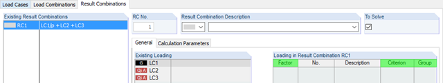
RFEM and RSTAB provides two different methods for the superposition of load cases. Using load combinations, the loads of individual load cases are superimposed and calculated in a "big load case". On the other hand, result combinations only combine the results of the individual load cases. This article describes the with the basis of defining result combinations and explain it in detail on two examples.