232 Results
View Results:
Sort by:
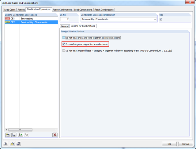
According to DIN EN 1990/NA:2010‑12 - NDP to A.1.2.1(1) Comment 2, it is possible to neglect the combination of snow as a collateral action in cases of wind/snow combination with wind as the leading action in wind zones III and IV.

In addition to the basic combination rules of EN 1990, there are other combination conditions for actions on road bridges specified in EN 1991‑2 that must be taken into account. RFEM and RSTAB provide automatic combinatorics that can be activated in the General Data when selecting the standard EN 1990 + EN 1991‑2. The partial safety factors and combination coefficients depending on the action category are preset when selecting the respective National Annex.

In RF‑/FOUNDATION Pro, the available reinforcing steel diameters can be adjusted by the user. The adjustment of the available rebar diameters works similarly to the same function in the RF‑/CONCRETE (Members) and RF‑/CONCRETE Columns add‑on modules.
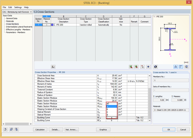
You can adjust the buckling curve of a cross-section in RF-/STEEL EC3, if necessary. This can be done in Window 1.3, Cross‑Sections.

In RF‑/FOUNDATION Pro, reinforcement drawings are displayed after designing the foundation, where you can record all necessary structures of the reinforcement steel.

For relatively large or relatively small surfaces, it can happen that the automatically created result values do not fit the model: In the case of large surfaces, there can be too many result values; in the case of small surfaces, too few.
.png?mw=640&hash=8fd04a597cecae2e434980ce79fc626815a5d98a)
The Aluminum Design Manual (ADM) 2020 was released in February 2020. The ADM 2020 gives guidance for both the allowable strength design (ASD) and load and resistance factor design (LRFD) for aluminum members to ensure reliability and safety for all aluminum structures. This latest standard was integrated in the RFEM/RSTAB add-on module RF-/ALUMINUM ADM. The text below will highlight the applicable updates relevant to the Dlubal programs.

When designing bending-resistant connections from I-beams, the connection is dissolved into the individual parts. For these basic components of a joint, there are separate formula calculators for load-bearing capacity and stiffness. In RFEM and RSTAB, frame joints can be designed using the RF-/FRAME-JOINT Pro add-on module.
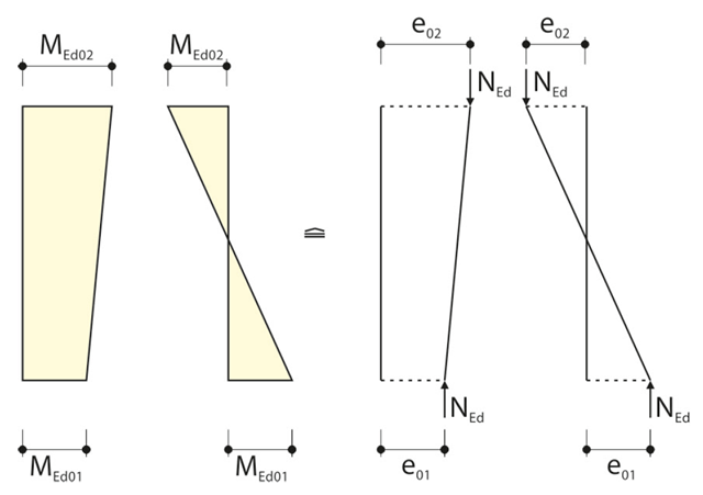
When calculating the internal forces for the buckling analysis with the method based on nominal curvature in RF‑CONCRETE Columns, the required eccentricities have to be determined.

In RF‑/STEEL EC3, you can assign the same input data to several members or sets of members at the same time. The simultaneous assignment of the input data is possible for intermediate supports, effective lengths, nodal supports, member end hinges, and shear panel and rotational restraint.
When determining the minimum reinforcement for the serviceability limit state according to 7.3.2, the applied effective tensile strength fct,eff has a significant influence on the determined amount of reinforcement. The following article gives an overview about determining the effective tensile strength fct,eff and the input options in RF-CONCRETE.

The automatic surface reinforcement design process determines a surface reinforcement that covers the required amount of reinforcement.

The classification of cross-sections according to EN 1993‑1‑1 and EN 1993‑1‑5 can be carried out automatically in the RF‑/STEEL EC3 add-on module. The maximum c/t ratios are specified in the standard for straight cross-section parts. There are no normative specifications for curved cross-section parts; therefore, the cross-section classification cannot be performed for these cross-section parts.

When defining the effective slab width of T-beams, RFEM provides the predefined widths that are determined as 1/6 and 1/8 of the member length. A more detailed explanation on these two factors is given below.

This article describes how a flat slab of a residential building is modeled in RFEM 6 and designed according to Eurocode 2. The plate is 24 cm thick and is supported by 45/45/300 cm columns at distances of 6.75 m in both the X and Y directions (Image 1). The columns are modeled as elastic nodal supports by determining the spring stiffness based on the boundary conditions (Image 2). C35/45 concrete and B 500 S (A) reinforcing steel are selected as the materials for the design.

In January 2015, DIN Committee NA 005‑08‑23 Steel Bridges applied the introduction of a modification in equation 10.5 of DIN EN 1993‑1‑5. This involves the interaction of longitudinal and transverse pressure in a buckling analysis. Now, the interaction equation provides for auxiliary factor V, which is calculated from the reduction factors of the longitudinal and transverse stresses.

The buckling analysis of plates with stiffeners is a special task for engineers. For this, EN 1993-1-5 provides three calculation methods: Effective Cross-Section Method, [1], Sect. 4-7; Reduced Stress Method, [1], Sect. 10; Finite Element Methods of Analysis (FEM), [1], Annex C.

In this example, the design resistance of an end plate according to EN 1993-1-8 [1] is to be determined; the other components are not described here. To check the results, the dimensions of the connection IH 3.1 B 30 24 of Typified Connections [2] were used. S 235 material and bolts with strength 10.9 are used.

This article deals with elements concerning which the cross-section is subjected simultaneously to a bending moment, a shear force, and an axial compressive or tensile force. However, in our example we will not include loading due to shear force.

Prior to the analysis of steel cross‑sections, the cross‑sections are classified according to EN 1993‑1‑1, Sec. 5.5, with respect to their resistance and rotation capacity. Thus, the individual cross-section parts are analyzed and assigned to Classes 1 to 4. The cross-section classes are determined subsequently and usually assigned to the highest class of the cross-section parts. If plastic resistance is to be applied to further design of cross-sections of Class 1 and Class 2, you can analyze the elastic resistance of cross-sections as of Class 3. In the case of cross-sections of Class 4, local buckling occurs even before reaching the elastic moment. In order to take this effect into account, you can use effective widths. This article describes the calculation of the effective cross-section properties in more detail.