271 Results
View Results:
Sort by:
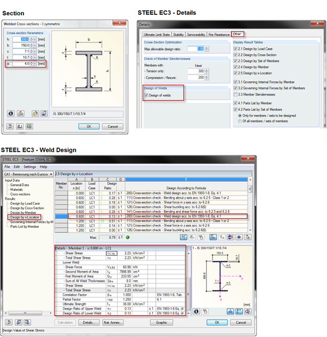
When using a welded profile, weld seam verification can also be carried out in RF-/STEEL EC3 as part of the design. The program performs the typical designs according to EN 1993‑1‑8.

Diagonals of double angles are used for pipe bridge construction and for truss girders, among other things. They are usually subjected to tension, but it is necessary to transfer them in smaller compression forces with regard to the load application. In the case of slender diagonals in particular, you should also consider the bending due to self‑weight.

A previous article describes the design of double angles. It deals with analysis performed on a single member.
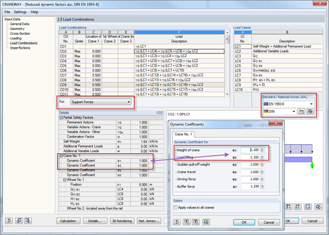
NCI to DIN EN 1993‑6, Part 2.3.1 allows reductions of dynamic coefficients for values ≧ 1.1. Therefore, you can use these reduced support loads for designing support and hanger structures. In CRANEWAY, if you select National Annex "DIN" and dynamic coefficients ≧ 1.1, the reduction is considered automatically.
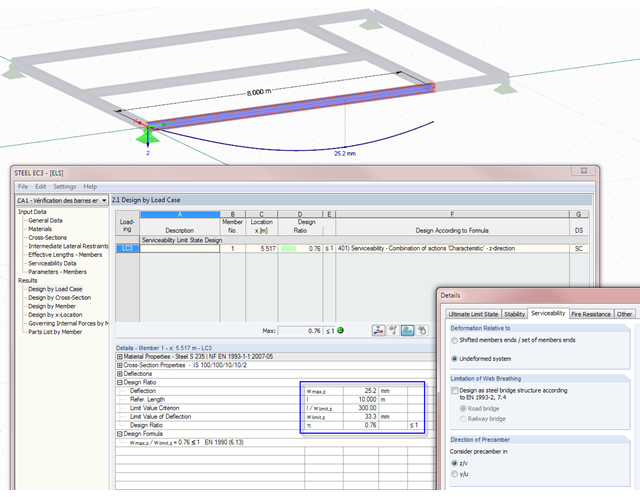
Not only do RF-/STEEL EC3 and RF-/TIMBER Pro perform cross-section designs and stability analyses, they allow you to perform serviceability limit state designs. For this, it is possible to relate the deformation to the undeformed initial system or to shifted members ends.

In January 2015, DIN Committee NA 005‑08‑23 Steel Bridges applied the introduction of a modification in equation 10.5 of DIN EN 1993‑1‑5. This involves the interaction of longitudinal and transverse pressure in a buckling analysis. Now, the interaction equation provides for auxiliary factor V, which is calculated from the reduction factors of the longitudinal and transverse stresses.

For structural reasons, shear connections usually include fin plates or flange angles. Main and secondary beams arranged on the top edge require notching or long fin plates. Hinged end plate connections are often welded to the web.

Torsional buckling analysis of transverse and longitudinal stiffeners with open cross-sections is described in DIN EN 1993-1-5, Chapter 9. There is a difference between the simplified method and the precise method, which takes into consideration the warping stiffness of the buckling panel. The simplified method applies Equation 9.3 of DIN EN 1993‑1‑5. If warping stiffness is to be taken into account, either Eq. 9.3 or Eq. 9.4 should be followed. Both design methods are implemented in PLATE-BUCKLING.
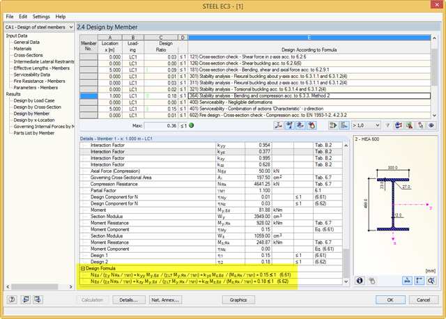
RF-/STEEL EC3 performs the classification, cross‑section designs, serviceability limit state designs, and fire resistance designs of members. For each design, the program shows a result table with the relevant values and classification numbers, including information regarding the respective standard clause. In order to identify the conjunction of various standards easily, there is a final design equation, including all terms, at the end of the table.
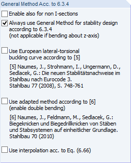
In addition to the stability designs according to EN 1993‑1‑1, Sections 6.3.1 through 6.3.3, you can apply the General Method according to EN 1993‑1‑1, 6.3.4 in RF‑/STEEL EC3.

The national parameters of EN 1992‑1‑1 for each country can be exported from RF‑/CONCRETE, RF‑/CONCRETE Columns, and RF‑/FOUNDATION Pro. To do this, there are interfaces with MS Excel, OpenOffice, and CSV. By exporting the national parameters, you can edit them in (for example) MS Excel, and display possible differences between the individual National Annexes clearly (see the image).

In the following example, the stability analysis of a steel frame can be performed according to the General Method in compliance with EN 1993‑1‑1, Sect. 6.3.4 in the RF‑/STEEL EC3 add-on module. The first of my three posts shows the determination of the critical load factor for design loads required by the design concept, which reaches the elastic critical buckling load with deformations from the main framework plane.
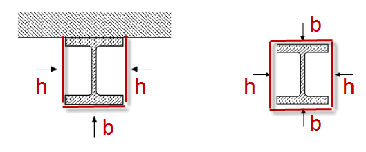
For unprotected I‑sections, the standard provides the correction factor ksh according to Equation 4.26a in Section 4.2.5.1 (2) to consider the shadowing effect. The term [Am/V]b is used there. This section factor includes Am, which represents the box enclosing the cross‑section (Index b = boxed). In the case of a three-sided fire exposure (a girder with a massive ceiling), the flange surface not exposed to fire is not taken into account when determining [Am/V]b.

In RF-STEEL Surfaces, it is possible to display the stresses relevant for the design of welds, for example, according to EN 1993‑1‑8, Figure 4.5. When evaluating the stress components, the local xyz-axis system of the surfaces must be considered.
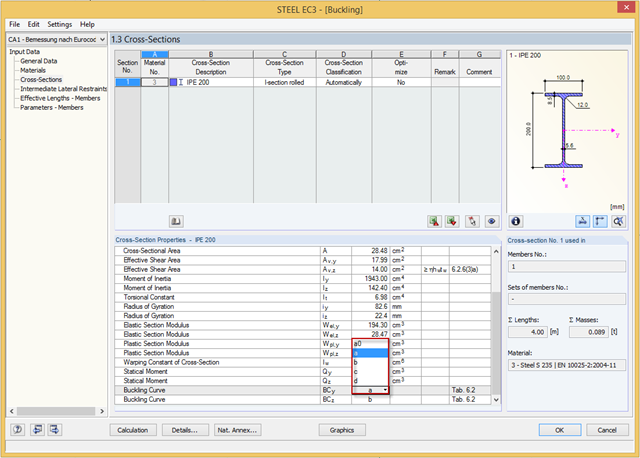
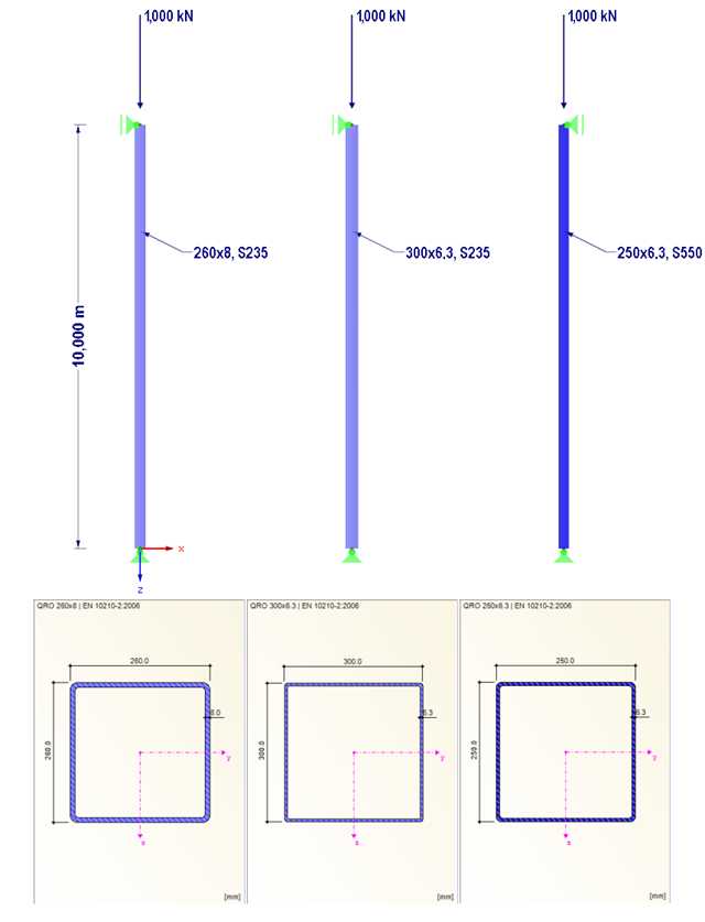
You can adjust the buckling curve of a cross-section in RF-/STEEL EC3, if necessary. This can be done in Window 1.3, Cross‑Sections.

RF‑/FOUNDATION Pro introduced the geotechnical design of single foundations according to EN 1997‑1 in RFEM 5 and RSTAB 8. Depending on the National Annex preset in the add‑on module, you can determine the bearing resistance using Approach 2 or 3 in compliance with EN 1997‑1 up to Version x.04.0108.

In RF‑/TIMBER Pro, it is also possible to define the effective length for lateral-torsional buckling. The effective length for lateral-torsional buckling is then calculated according to EN 1995‑1‑1, Table 6.1. This option is useful especially for non-uniform load introduction.

Various optimizations are available with program version x.06.1103. The RF-/FOUNDATION Pro add-on module has also been subjected to further development.

The buckling analysis of plates with stiffeners is a special task for engineers. For this, EN 1993-1-5 provides three calculation methods: Effective Cross-Section Method, [1], Sect. 4-7; Reduced Stress Method, [1], Sect. 10; Finite Element Methods of Analysis (FEM), [1], Annex C.
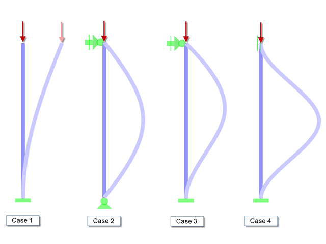
When performing the stability analysis of members according to the equivalent member method, considering internal forces according to the linear static analysis, it is very important to determine the governing equivalent member lengths.

The following article describes the design of a single-span beam subjected to bending and compression, which is performed according to EN 1993‑1‑1 in the RF-/STEEL EC3 add-on module. Since the beam is modeled with a tapered cross-section and thus it is not a uniform structural component, the design must be performed either according to General Method in compliance with Sect. 6.3.4 of EN 1993‑1‑1, or according to the second-order analysis. Both options will be explained and compared, and for the calculation according to the second-order analysis, there is an additional design format using Partial Internal Forces Method (PIFM) available. Therefore, the design is divided into three steps: design according to Sect. 6.3.4 of EN 1993‑1‑1 (General Method), design according to the second‑order analysis, elastic (warping torsion analysis), design according to the second‑order analysis, plastic (warping torsion analysis and Partial Internal Forces Method).

The RF-/STEEL EC3 add‑on module performs a detailed cross‑section classification on each design before the design is carried out. Thus, the susceptibility to local buckling of all cross-section parts is evaluated. The defined cross-section class has an effect on the resistance and rotational capacity determination.
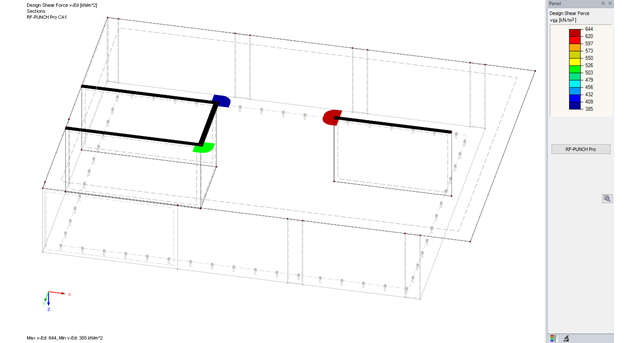
The RF-PUNCH Pro add-on module allows you to perform punching shear design of slabs and foundation plates (floor slabs) on wall ends and wall corners.

For structural components consisting of slabs, it is necessary to perform shear design on the locations with concentrated load introduction, applying the punching shear design rules according to Sect. 6.4 of EN 1992‑1‑1 [1]. The concentrated load introduction is present on the individual locations; for example, by columns, concentrated load, or nodal supports. In addition, the end of linear load introduction on slabs is also regarded as concentrated load introduction. For example, this includes wall ends, wall corners, and ends or corners of line loads and line supports. You can perform the punching shear design for floor slabs or foundations, considering the existing available plate topology about the designed node of punching shear. The punching shear design according to EN 1992‑1‑1 checks that the acting shear force vEd does not exceed the resistance vRd.

Prior to the analysis of steel cross‑sections, the cross‑sections are classified according to EN 1993‑1‑1, Sec. 5.5, with respect to their resistance and rotation capacity. Thus, the individual cross-section parts are analyzed and assigned to Classes 1 to 4. The cross-section classes are determined subsequently and usually assigned to the highest class of the cross-section parts. If plastic resistance is to be applied to further design of cross-sections of Class 1 and Class 2, you can analyze the elastic resistance of cross-sections as of Class 3. In the case of cross-sections of Class 4, local buckling occurs even before reaching the elastic moment. In order to take this effect into account, you can use effective widths. This article describes the calculation of the effective cross-section properties in more detail.
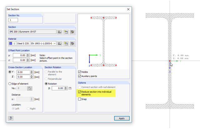
SHAPE‑THIN cross‑section properties software determines the effective section properties of thin‑walled cross‑sections according to Eurocode 3 and Eurocode 9. Alternatively, the program allows plastic design of general cross‑sections according to the Simplex Method. In this process, plastic cross-section reserves are iteratively calculated for elastically determined internal forces. The following example describes the effective cross-section properties in the notching area of a rolled I-section. Afterwards, the results are compared with the plastic analysis.
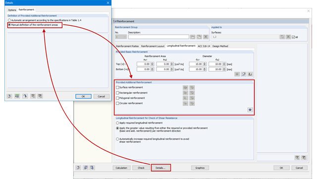
As an alternative to the conventional automatic arrangement of surface reinforcement in RF-CONCRETE Surfaces, it is also possible to set it according to the individual requirements. This is advantageous for the creation of reinforcement drawings, for example, as the reinforcement areas can be clearly defined and dimensioned.
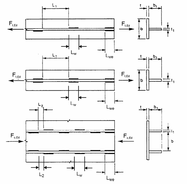
If crane runway girders are designed with flat steel rails, the welding of these rails is always a detail for the design. You can generally select between continuous and intermittent fillet welds as a rail fixing. The following article provides an overview of the design processes and their specific features, especially when using EN 1993-6.
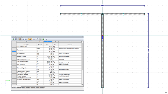
The design of cross-sections usually requires many different cross-section properties. In RFEM and RSTAB, all required properties of standardized cross-sections are available in the cross-section library and can be used directly for the calculation. If the cross-sections are not standardized, SHAPE-THIN allows you to use these cross-sections, too. You can simply enter the geometry to determine all required cross-section properties. The following example shows the calculation of a shear area on a practical example.