
When generating shear walls and deep beams, you can assign not only surfaces and cells, but also members.

You can neglect openings with a certain area in the building model calculation. This function can be activated in the global settings of the building stories. A warning message appears saying that the openings have been neglected.

The building story generator in the Building Model add-on allows you to automatically create building stories, depending on the topology of the model.

For a response spectrum analysis of building models, you can display the sensitivity coefficients for the horizontal directions by story.
These key figures allow you to interpret the sensitivity to stability effects.

The Timber Design add-on for RFEM 6 / RSTAB 9 is multi-purpose and combines a large number of additional elements. [*S16332764*] Timber Design Add-on for RFEM 6

You can display the results as usual via the Results navigator. Furthermore, the dialog box of the add-on shows you the information about the individual floors. Thus, you always have a good overview.

Shear walls and deep beams of a building model are available as independent objects in the design add-ons. This allows for faster filtering of the objects in results, as well as better documentation in the printout report.

You have two options for a building model. You can create it when you start modeling the structure, or activate it afterwards. In the building model, you can then directly define the stories and manipulate them.
When manipulating the stories, you can choose whether to modify or retain the included structural elements using various options.
RFEM does some of the work for you. For example, it automatically generates result sections, so you don't need to perform a lot of calculations.

You find the serviceability limit state design fully integrated in the result tables of the Timber Design add-on. If yuo want to check the design results, you can open the program and display the results with all the details at each location of the designed members. Furthermore, graphics are available for you with the result diagrams of the design ratios.
A special thing is that All result tables and graphics can be integrated into the global printout report of RFEM/RSTAB as a part of the timber design results. You can also display and document the deformations of the entire structure as a part of the RFEM/RSTAB functionality. This function is independent of the add-on.

Are you still looking for the design? The design checks are available in tabular form in the Timber Design add-on. Moreover, the program can also show you the distribution of the design ratios graphically. Extensive filter options are available for you in the table as well as in the graphical output, and you can use them to display the desired design checks by limit state or design type.

- Arbitrary definition of the charring time
- Option to calculate with or without adhesion of the layer for surface structures (cross-laminated timber)
- Free user-defined specification of the fire parameters
- Consideration of Different Effective Lengths in Fire Resistance Design
- Optional design "Compression perpendicular to grain"
- Graphical result display integrated in RFEM/RSTAB, such as a design ratio
- Complete integration of the results into the RFEM/RSTAB printout report

Your RFEM/RSTAB program is responsible for generating and calculating the load and result combinations required for the serviceability limit state. Select the design situations for the deflection analysis in the Timber Design add-on. The calculated deformation values are then determined at each location of a member, depending on the specified precamber and the reference system, and then compared to the limit values.
You can specify the deformation limit value individually for each structural component in Serviceability Configuration. In this case, the maximum deformation should not exceed the permissible limit value, depending on the reference length. When defining design supports, you can segment the components. This allows you to determine the corresponding reference length automatically for each design direction.
Based on the position of the assigned design supports, the program automatically determines the difference between beams and cantilevers. Thus, you can be sure that the limit value is determined accordingly.

You have the option to perform the fire resistance design of surfaces using the reduced cross-section method. The reduction is applied over the surface thickness. It is possible to perform the design checks for all timber materials allowed for the design.
For cross-laminated timber, depending on the type of adhesive, you can select whether it is possible for individual carbonized layer parts to fall off, and whether you can expect increased charring in certain layer areas.

- A wide range of cross-sections, such as rectangular sections, square sections, T‑sections, circular sections, built-up cross-sections, irregular parametric cross-sections, and many others (suitability for design depends on the selected standard)
- Design of cross-laminated timber (CLT)
- Design of timber-based materials and laminated veneer lumber according to EC 5
- Design of tapered and curved members (design method according to the standard)
- Adjustment of the essential design factors and standard parameters is possible
- Flexibility due to detailed setting options for basis and extent of calculations
- Fast and clear results output for an immediate overview of the result distribution after the design
- Detailed output of the design results and essential formulas (comprehensible and verifiable result path)
- Numerical results clearly arranged in tables and graphical display of the results in the model
- Integration of the output into the RFEM/RSTAB printout report

- Consideration and display of story masses
- Listing of structural elements and their information
- Automated creation of result sections on shear walls
- Output of section resultants in global direction for determining shear forces
- Optional definition of rigid diaphragm by story (story modeling)
- Stiffness type Floor Slab - Rigid Diaphragm
- Defining floor sets,
- for example, calculation of slabs as a 2D position within the 3D model
- Shear walls: Automatic definition of result members with any cross-section
- Design of rectangular cross-sections using the Concrete Design add-on
- Definition of deep beams
- Design with the Concrete Design add-on
- Tabular output of story actions, interstory drift, and center points of mass and stiffness, as well as the forces in shear walls
- Separate result display of the floor and stiffening design
- Optional neglecting of openings of a certain size

You can enter the structural system and calculate the internal forces in the programs RFEM and RSTAB. You have full access to the extensive material and cross-section libraries.
Timber Design is completely integrated into the main programs. At the same time, it automatically takes into account the structure and the available calculation results. You can assign further entries for the timber design, such as effective lengths, cross-section reductions, or design parameters, to the objects to be designed. You can easily select the elements graphically using the [Select] function at many places of the program.
For the design according to Eurocode 5, the parameters of the National Annexes (NA) are integrated for the following countries:
-
 DIN EN 1995-1-1/NA:2014-07 (Germany)
 -
 ÖNORM EN 1995-1-1/NA:2019-06 (Austria)
 -
 SN EN 1995-1-1/NA:2015-03 (Switzerland)
 -
 BDS EN 1995-1-1/NA:20157-06 (Bulgaria)
 -
 BS EN 1995-1-1/NA:2019-09 (United Kingdom)
 -
 CEN EN 1995-1-1/2014-05 (European Union)
 -
 CYS EN 1995-1-1/NA:2019-06 (Cyprus)
 -
 CZE EN 1995-1-1/NA:2015-05 (Czech Republic)
 -
 DS EN 1995-1-1/NA:2019-09 (Denmark)
 -
 ELOT EN 1995-1-1/NA:2010-01 (Greece)
 -
 EVS EN 1995-1-1/NA:2015-11 (Estonia)
 -
 HRN EN 1995-1-1/NA:2015-03 (Croatia)
 -
 I S. EN 1995-1-1/NA:2014-05 (Ireland)
 -
 ILNAS EN 1995-1-1/NA:2020-3 (Luxembourg)
 -
 IST EN 1995-1-1/NA:2014-09 (Iceland)
 -
 LST EN 1995-1-1/NA:2014-06 (Lithuania)
 -
 LVS EN 1995-1-1/NA:2014-12 (Latvia)
 -
 MSZ EN 1995-1-1/NA:2015-06 (Hungary)
 -
 NBN EN 1995-1-1/NA:2014-06 (Belgium)
 -
 NEN EN 1995-1-1/NA:2014-06 (Netherlands)
 -
 NF EN 1995-1-1/NA:2020-04 (France)
 -
 NP EN 1995-1-1/NA:2014-09 (Portugal)
 -
 NS EN 1995-1-1/NA:2014-08 (Norway)
 -
 PN EN 1995-1-1/NA:2014-07 (Poland)
 -
 SFS EN 1995-1-1/NA:2016-12 (Finland)
 -
 SIST EN 1995-1-1/NA:2018-01 (Slovenia)
 -
 SR EN 1995-1-1/NA:2014-12 (Romania)
 -
 SS EN 1995-1-1/NA:2018-02 (Singapore)
 -
 SS EN 1995-1-1/NA:2014-05 (Sweden)
 -
 STN EN 1995-1-1/NA:2019-12 (Slovakia)
 -
 TKP EN 1995-1-1/NA:2019-09 (Belarus)
 -
 UNE EN 1995-1-1/NA:2016-04 (Spain)
 -
 UNI EN 1995-1-1/NA:2016-11 (Italy)

- Calculation of deflections and comparison with the normative or manually adjusted limit values
- Consideration of a precamber for the deflection analysis
- Different limit values are possible, depending on the design situation type
- Manual adjustment of reference lengths and segmentation by direction
- Calculation of deflections related to the initial structure or to the deformed structure
- Automatic consideration of time-dependent deformations by increasing the load with the creep factor (can also be user-defined on the stiffness side)
- Simplified vibration design
- Graphical result display integrated in RFEM/RSTAB; for example, the design ratio of a limit value, the deformation, or the sag
- Complete integration of the results into the RFEM/RSTAB printout report

Did you know? You can individually define the reference lengths to be considered in the calculation of the deflection limit value and the segments to be checked, depending on the direction. For this, define design supports at the intermediate nodes of a member and assign them to the respective direction for the deformation analysis. In the resulting segments, you can also define a precamber for each direction and segment.

If your design is successful, the relaxed part of your work follows. Because the program does many processes for you. For example, the performed design checks are displayed in a table. It shows you all the result details. Due to the clearly presented design formulas, you will be able to understand the results without any problems. There is no "black box" effect here.
The design checks are carried out at all governing locations of the members and displayed graphically as a result diagram. Furthermore, detailed graphics, such as the stress distribution on a cross-section or the governing mode shape, are available for you in the result output.
All input and result data are part of the RFEM/RSTAB printout report. You can select the report contents and extent specifically for the individual design checks.

There is often no fire resistance design for the lateral supports of a structure. Would you like to handle this differently in your project? In order to consider this in the calculation, you can define other equivalent member lengths for the fire situation.

The form-finding process gives you a structural model with active forces in the "prestress load case" This load case shows the displacement from the initial input position to the form-found geometry in the deformation results. In the force or stress-based results (member and surface internal forces, solid stresses, gas pressures, and so on), it clarifies the state for maintaining the found form. For the analysis of the shape geometry, the program offers you a two-dimensional contour line plot with the output of the absolute height and an inclination plot for the visualization of the slope situation.
Now, a further calculation and structural analysis of the entire model is performed. For this purpose, the program transfers the form-found geometry including the element-wise strains into a universally applicable initial state. You can now use it in the load cases and load combinations.

The stress and strain results by surface can be output in the surface result table according to the thickness layer.

What happens when there is a downwind? The topside lateral-torsional bracing is not applied to reduce the effective lengths and lateral-torsional buckling lengths.

The Ponding load type allows you to simulate rain actions on multi-curved surfaces, taking into account the displacements according to the large deformation analysis.
This numerical rainfall process examines the assigned surface geometry and determines which rainfall portions drain away and which rainfall portions accumulate in puddles (water pockets) on the surface. The puddle size then results in a corresponding vertical load for the structural analysis.
For example, you can use this feature in the analysis of approximately horizontal membrane roof geometries subjected to rain loading.
Go to Explanatory Video
Once you activate the Form-Finding add-on in the Base Data, a form-finding effect is assigned to the load cases with the load case category "Prestress" in conjunction with the form-finding loads from the member, surface, and solid load catalog. This is a prestress load case. It thus mutates into a form-finding analysis for the entire model with all member, surface, and solid elements defined in it. You reach the form-finding of the relevant member and membrane elements amid the overall model by using special form-finding loads and regular load definitions. These form-finding loads describe the expected state of deformation or force after the form-finding in the elements. The regular loads describe the external loading of the entire system.

Is there torsion? In this case, you can decide how to perform the design. You have the following options:
- Allow further design if shear stress due to torsion does not exceed limit value
- Design according to Timber Construction Manual, 4.6
- Ignoring torsion

Dlubal Software just makes everything a little easier. The performed design checks of the design standard are displayed in a clear way. A design criterion is determined for each design check. Furthermore, the program deliver the design details displayed in a structured way, including the initial values, the intermediate results, and the final results. An information window in the design details shows you the calculation process with the applied formulas, standard sources, and results in great detail.
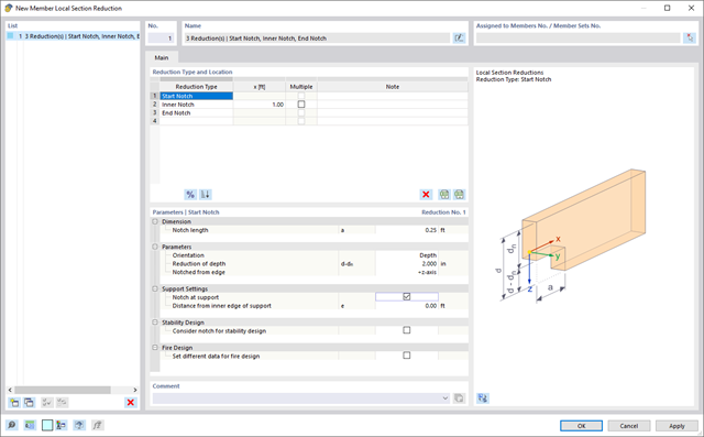
Use the member cross-section reductions to consider the start, internal, or end notches of a beam. The beam reduction is thus taken into account in the calculation of the load-bearing capacity. However, this does not apply to the stiffness.

Did you use the eigenvalue solver of the add-on to determine the critical load factor within the stability analysis? If so, you can then display the governing mode shape of the object to be designed as a result. The eigenvalue solver is available here for the lateral-torsional buckling analysis, depending on the design standard used.