
- For the design according to Eurocode 3, the parameters of the National Annexes (NA) are integrated for the following countries:
-
 DIN EN 1993-1-1/NA:2016-04 (Germany)
 -
 ÖNORM EN 1993-1-1/NA:2015-12 (Austria)
 -
 SN EN 1993-1-1/NA:2016-07 (Switzerland)
 -
 BDS EN 1993-1-1/NA:2015-10 (Bulgaria)
 -
 BS EN 1993-1-1/NA:2016-07 (United Kingdom)
 -
 CEN EN 1993-1-1/2015-06 (European Union)
 -
 CYS EN 1993-1-1/NA:2015-07 (Cyprus)
 -
 CZE EN 1993-1-1/NA:2016-06 (Czech Republic)
 -
 DS EN 1993-1-1/NA:2015-07 (Denmark)
 -
 ELOT EN 1993-1-1/NA:2017-01 (Greece)
 -
 EVS EN 1993-1-1/NA:2015-08 (Estonia)
 -
 HRN EN 1993-1-1/NA:2016-03 (Croatia)
 -
 I S. EN 1993-1-1/NA:2016-03 (Ireland)
 -
 ILNAS EN 1993-1-1/NA:2015-06 (Luxembourg)
 -
 IST EN 1993-1-1/NA:2015-11 (Iceland)
 -
 LST EN 1993-1-1/NA:2017-01 (Lithuania)
 -
 LVS EN 1993-1-1/NA:2015-10 (Latvia)
 -
 MS EN 1993-1-1/NA:2010-01 (Malaysia)
 -
 MSZ EN 1993-1-1/NA:2015-11 (Hungary)
 -
 NBN EN 1993-1-1/NA:2015-07 (Belgium)
 -
 NEN EN 1993-1-1/NA:2016-12 (Netherlands)
 -
 NF EN 1993-1-1/NA:2016-02 (France)
 -
 NP EN 1993-1-1/NA:2009-03 (Portugal)
 -
 NS EN 1993-1-1/NA:2015-09 (Norway)
 -
 PN EN 1993-1-1/NA:2015-08 (Poland)
 -
 SFS EN 1993-1-1/NA:2015-08 (Finland)
 -
 SIST EN 1993-1-1/NA:2016-09 (Slovenia)
 -
 SR EN 1993-1-1/NA:2016-04 (Romania)
 -
 SS EN 1993-1-1/NA:2019-05 (Singapore)
 -
 SS EN 1993-1-1/NA:2015-06 (Sweden)
 -
 STN EN 1993-1-1/NA:2015-10 (Slovakia)
 -
 TKP EN 1993-1-1/NA:2015-04 (Belarus)
 -
 UNE EN 1993-1-1/NA:2016-02 (Spain)
 -
 UNI EN 1993-1-1/NA:2015-08 (Italy)
-
- The design according to US standard AISC 360 includes analysis methods according to:
-
 Load and Resistance Factor Design (LRFD)
 -
Allowable Stress Design (ASD)
-

The parameters of the National Annexes (NA) to Eurocode 3 of the following countries are integrated:
-
DIN EN 1993-1-1/NA:2016-04 (Germany)
-
ÖNORM EN 1993-1-1/NA:2015-12 (Austria)
-
SN EN 1993-1-1/NA:2016-07 (Switzerland)
-
BDS EN 1993-1-1/NA:2015-10 (Bulgaria)
-
BS EN 1993-1-1/NA:2016-07 (United Kingdom)
-
CEN EN 1993-1-1/2015-06 (European Union)
-
CYS EN 1993-1-1/NA:2015-07 (Cyprus)
-
CSN EN 1993-1-1/NA:2016-06 (Czech Republic)
-
DS EN 1993-1-1/NA:2015-07 (Denmark)
-
ELOT EN 1993-1-1/NA:2017-01 (Greece)
-
EVS EN 1993-1-1/NA:2015-08 (Estonia)
-
HRN EN 1993-1-1/NA:2016-03 (Croatia)
-
I S. EN 1993-1-1/NA:2016-03 (Ireland)
-
ILNAS EN 1993-1-1/NA:2015-06 (Luxembourg)
-
IST EN 1993-1-1/NA:2015-11 (Iceland)
-
LST EN 1993-1-1/NA:2017-01 (Lithuania)
-
LVS EN 1993-1-1/NA:2015-10 (Latvia)
-
MS EN 1993-1-1/NA:2010-01 (Malaysia)
-
MSZ EN 1993-1-1/NA:2015-11 (Hungary)
-
NBN EN 1993-1-1/NA:2015-07 (Belgium)
-
NEN EN 1993-1-1/NA:2016-12 (Netherlands)
-
NF EN 1993-1-1/NA:2016-02 (France)
-
NP EN 1993-1-1/NA:2009-03 (Portugal)
-
NS EN 1993-1-1/NA:2015-09 (Norway)
-
PN EN 1993-1-1/NA:2015-08 (Poland)
-
SFS EN 1993-1-1/NA:2015-08 (Finland)
-
SIST EN 1993-1-1/NA:2016-09 (Slovenia)
-
SR EN 1993-1-1/NA:2016-04 (Romania)
-
SS EN 1993-1-1/NA:2019-05 (Singapore)
-
SS EN 1993-1-1/NA:2015-06 (Sweden)
-
STN EN 1993-1-1/NA:2015-10 (Slovakia)
-
TKP EN 1993-1-1/NA:2015-04 (Belarus)
-
UNE EN 1993-1-1/NA:2016-02 (Spain)
-
UNI EN 1993-1-1/NA:2015-08 (Italy)

- Manual specification of critical component temperature or automatic determination of component temperature for desired duration
- A wide range of fire curves: standard temperature-time curve, external fire curve, hydrocarbon curve
- Manual adjustment of the essential coefficients for the determination of the steel temperature
- Consideration of hot-dip galvanizing of structural components for the determination of the steel temperature
- Results of a temperature-time diagram for the gas and steel temperature
- Fire protection cladding as a contour or a box cladding with temperature-independent materials can be considered when determining the temperature
- Design of members made of carbon steel or stainless steel
- Cross-section design checks and stability analyses (equivalent member method) according to EN 1993‑1‑2, Clause 4.2.3
- Design checks of the cross-sections of Class 4 according to EN 1993‑1‑2, Annex E.

- Calculation of deflections and comparison with the normative or manually adjusted limit values
- Consideration of a precamber for the deflection analysis
- Different limit values are possible, depending on the design situation type
- Manual adjustment of reference lengths and segmentation by direction
- Calculation of deflections related to the initial structure or to the deformed structure
- Further detailed design checks depending on the selected design standard (for example, limitation of web breathing according to EN 1993‑2)
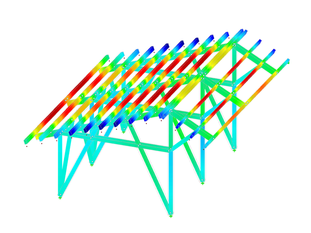
- Graphical result display integrated in RFEM/RSTAB; for example, the design ratio of a limit value, the deformation, or the sag
- Complete integration of the results into the RFEM/RSTAB printout report
_(1).png?mw=640&hash=415f7bbaf70e41679bb0106e1cf91eaa8c493ec9)
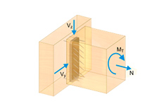
- Automatic generation of FE analysis models: The add-on automatically creates a finite element model (FE) of the steel connection in the background.
- Consideration of all internal forces: The calculation and design checks include all internal forces (N, Vy, Vz, My, Mz, MT) and are not limited to planar loading.
- Automatic load transfer: All load combinations are automatically transferred to the FE analysis model of the connection. The loads are transferred directly from RFEM, so manual data input is not necessary.
- Efficient modeling: The add-on saves you time when modeling complex connection situations. You can also save the created FE analysis model and use it further for your own detailed analyses.
- Extensible library: An extensive and extensible library with predefined steel connection templates is available.
- Wide applicability: The add-on is suitable for connections of any type and shape, compatible with almost all rolled, welded, built-up, and thin-walled cross-sections.

The pushover analysis is managed by a newly introduced analysis type in the load combinations. Here, you have access to the selection of the horizontal load distribution and direction, the selection of a constant load, the selection of the desired response spectrum for the determination of the target displacement, and the pushover analysis settings tailored to the pushover analysis.
In the pushover analysis settings, you can modify the increment of the increasing horizontal load and specify the stopping condition for the analysis. Furthermore, it is possible to easily adjust the precision for the iterative determination of the target displacement.

You have several options available to define masses for a modal analysis. While the masses due to self-weight are considered automatically, you can consider the loads and masses directly in a load case of the modal analysis type. Do you need more options? Select whether to consider full loads as masses, load components in the global Z-direction, or only the load components in the direction of gravity.
The program offers you an additional or alternative option for importing masses: A manual definition of load combinations as of which are the masses considered in the modal analysis. Have you selected a design standard? You can then create a design situation with the Seismic Mass combination type. Thus, the program automatically calculates a mass situation for the modal analysis according to the preferred design standard. In other words: The program creates a load combination on the basis of the preset combination coefficients for the selected standard. This contains the masses used for the modal analysis.

In RFEM, you can use these three powerful eigenvalue solvers:
- Root of Characteristic Polynomial
- Method by Lanczos
- Subspace Iteration
RSTAB, on the other hand, provides you with these two eigenvalue solvers:
- Subspace Iteration
- Shifted inverse power method
The selection of the eigenvalue solver depends primarily on your model size.

- Consideration of nonlinear component behavior using plastic standard hinges for steel (FEMA 356, EN 1998‑3) and nonlinear material behavior (masonry, steel - bilinear, user-defined working curves)
- Direct import of masses from load cases or combinations for the application of constant vertical loads
- User-defined specifications for the consideration of horizontal loads (standardized to a mode shape or uniformly distributed over the height of the masses)
- Determination of a pushover curve with selectable limit criterion of the calculation (a collapse or limit deformation)
- Transformation of the pushover curve into the capacity spectrum (ADRS format, single degree of freedom system)
- Bilinearization of the capacity spectrum according to EN 1998‑1:2010 + A1:2013
- Transformation of the applied response spectrum into the required spectrum (ADRS format)
- Determination of target displacement according to EC 8 (the N2 method according to Fajfar 2000)
- Graphical comparison of the capacity and required spectrum
- Graphical evaluation of the acceptance criteria of predefined plastic hinges
- Result display of the values used in the iterative calculation of the target displacement
- Access to all results of the structural analysis in the individual load levels

You enter the structural system and calculate the internal forces in the programs RFEM and RSTAB. You have full access to the extensive material and cross-section libraries. Did you know? You can also use the RSECTION program to create general cross-sections.
You find Steel Design fully integrated in the main programs. They automatically take into account the structure and the available calculation results. You can assign further entries for the aluminum design, such as effective lengths, cross-section reductions, or design parameters, to the objects to be designed. At many places of the program, you can easily select the elements graphically using the [Select] function.
- Design of members and continuous members for tension, compression, bending, shear, and combined internal forces
- Stability analysis for lateral-torsional buckling and buckling according to the equivalent member method or the second order analysis
- Serviceability limit state design by limitation of deflections
- Free configuration of charring time and charring rates, as well as free choice of charring sides for fire design
- Design of tapered and curved beams consisting of glulam timber
- Material and cross‑section library based on the Canadian standard
- User-defined entry of rectangular and circular cross-sections
- Automatic cross-section optimization
- Optional import of buckling lengths from the RF-STABILITY/RSBUCK module
- Detailed result documentation including references to design equations of the used standard
- Various filtering and sorting options of results
- Consideration of moisture service conditions
- Visualization of design criterion on RFEM/RSTAB model
- Data export to MS Excel
- Units metric and imperial

You find the serviceability limit state design fully integrated in the result tables of the Timber Design add-on. If yuo want to check the design results, you can open the program and display the results with all the details at each location of the designed members. Furthermore, graphics are available for you with the result diagrams of the design ratios.
A special thing is that All result tables and graphics can be integrated into the global printout report of RFEM/RSTAB as a part of the timber design results. You can also display and document the deformations of the entire structure as a part of the RFEM/RSTAB functionality. This function is independent of the add-on.

- Automatic consideration of masses from self-weight
- Direct import of masses from load cases or load combinations
- Optional definition of additional masses (nodal, linear, or surface masses, as well as inertia masses) directly in the load cases
- Optional neglect of masses (for example, mass of foundations)
- Combination of masses in different load cases and load combinations
- Preset combination coefficients for various standards (EC 8, SIA 261, ASCE 7,...)
- Optional import of initial states (for example, to consider prestress and imperfection)
- Structure Modification
- Consideration of failed supports or members/surfaces/solids
- Definition of several modal analyses (for example, to analyze different masses or stiffness modifications)
- Selection of mass matrix type (diagonal matrix, consistent matrix, unit matrix), including user-defined specification of translational and rotational degrees of freedom
- Methods for determining the number of mode shapes (user-defined, automatic - to reach effective modal mass factors, automatic - to reach the maximum natural frequency - only available in RSTAB)
- Determination of mode shapes and masses in nodes or FE mesh points
- Results of eigenvalue, angular frequency, natural frequency, and period
- Output of modal masses, effective modal masses, modal mass factors, and participation factors
- Masses in mesh points displayed in tables and graphics
- Visualization and animation of mode shapes
- Various scaling options for mode shapes
- Documentation of numerical and graphical results in printout report

- A wide range of available sections, such as rolled I-sections; channel sections; T-sections; angles; rectangular and circular hollow sections; round bars; symmetrical and asymmetrical, parametric I-, T-, and angle sections; built-up cross-sections (suitability for design depends on the selected standard)
- Design of general RSECTION cross-sections (depending on the design formats available in the respective standard); for example, equivalent stress design
- Design of tapered members (design method depending on the standard)
- Adjustment of the essential design factors and standard parameters is possible
- Flexibility due to detailed setting options for basis and extent of calculations
- Fast and clear results output for an immediate overview of the result distribution after the design
- Detailed output of the design results and essential formulas (comprehensible and verifiable result path)
- Numerical results clearly arranged in tables and graphical display of the results in the model
- Integration of the output into the RFEM/RSTAB printout report

Are you still looking for the design? The design checks are available in tabular form in the Timber Design add-on. Moreover, the program can also show you the distribution of the design ratios graphically. Extensive filter options are available for you in the table as well as in the graphical output, and you can use them to display the desired design checks by limit state or design type.
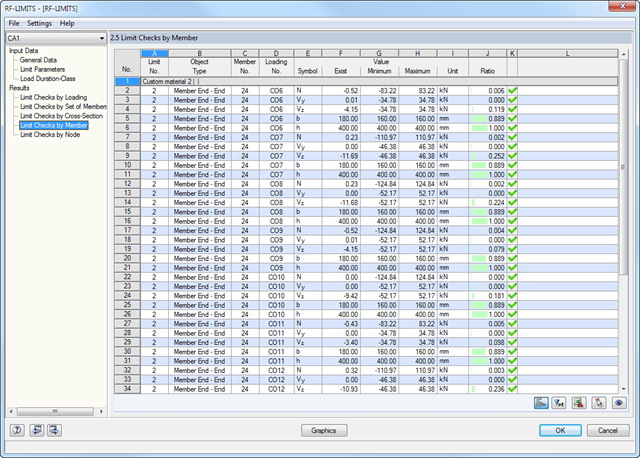
First, the governing design checks of the connection for the respective load case, and load combination, or result combination are displayed. In addition, it is possible to display results separately for sets of members, surfaces, cross-section, members, nodes, and nodal supports.
- You can use a filter to further reduce the displayed results and thus present them in a clearer way.
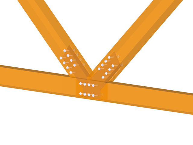
- Design of hinged, bending resistant, and semi-rigid connections
- Definition of up to 5 steel plates slotted in timber beams
- Up to 8 members connected to one node
- Thickness of steel plate 5 mm – 40 mm
- All sizes of fasteners
- Automatic check of the minimum distance between fasteners
- Optional free definition of fastener distances
- Definition of asymmetrical fastener arrangements (for example, any polygonal chains)
- Graphical visualization of joints in the add-on module and in RFEM/RSTAB
- All required steel and timber designs, including reduction of cross‑section values
- Design of transversal tension reinforcement (for EN 1995‑1‑1 only)
- Export of the member eccentricities to RFEM/RSTAB to be considered in the determination of internal forces
- Dowel length optionally shorter than cross-section width (for wooden plugs)
- DXF Export of Connection Geometry
- Fire resistance design according to EN 1995‑1‑2

- Arbitrary definition of the charring time
- Option to calculate with or without adhesion of the layer for surface structures (cross-laminated timber)
- Free user-defined specification of the fire parameters
- Consideration of Different Effective Lengths in Fire Resistance Design
- Optional design "Compression perpendicular to grain"
- Graphical result display integrated in RFEM/RSTAB, such as a design ratio
- Complete integration of the results into the RFEM/RSTAB printout report

Your RFEM/RSTAB program is responsible for generating and calculating the load and result combinations required for the serviceability limit state. Select the design situations for the deflection analysis in the Timber Design add-on. The calculated deformation values are then determined at each location of a member, depending on the specified precamber and the reference system, and then compared to the limit values.
You can specify the deformation limit value individually for each structural component in Serviceability Configuration. In this case, the maximum deformation should not exceed the permissible limit value, depending on the reference length. When defining design supports, you can segment the components. This allows you to determine the corresponding reference length automatically for each design direction.
Based on the position of the assigned design supports, the program automatically determines the difference between beams and cantilevers. Thus, you can be sure that the limit value is determined accordingly.

You have the option to perform the fire resistance design of surfaces using the reduced cross-section method. The reduction is applied over the surface thickness. It is possible to perform the design checks for all timber materials allowed for the design.
For cross-laminated timber, depending on the type of adhesive, you can select whether it is possible for individual carbonized layer parts to fall off, and whether you can expect increased charring in certain layer areas.

In the modal analysis settings, you have to enter all data that are necessary for the determination of the natural frequencies. These are, for example, mass shapes and eigenvalue solvers.
The Modal Analysis add-on determines the lowest eigenvalues of the structure. Either you adjust the number of eigenvalues or let them determined automatically. Thus, you should reach either effective modal mass factors or maximum natural frequencies. Masses are imported directly from load cases and load combinations. In this case, you have the option to consider the total mass, load components in the global Z-direction, or only the load component in the direction of gravity.
You can manually define additional masses at nodes, lines, members, or surfaces. Furthermore, you can influence the stiffness matrix by importing axial forces or stiffness modifications of a load case or load combination.
- A wide range of cross-sections, such as rectangular sections, square sections, T‑sections, circular sections, built-up cross-sections, irregular parametric cross-sections, and many others (suitability for design depends on the selected standard)
- Design of cross-laminated timber (CLT)
- Design of timber-based materials and laminated veneer lumber according to EC 5
- Design of tapered and curved members (design method according to the standard)
- Adjustment of the essential design factors and standard parameters is possible
- Flexibility due to detailed setting options for basis and extent of calculations
- Fast and clear results output for an immediate overview of the result distribution after the design
- Detailed output of the design results and essential formulas (comprehensible and verifiable result path)
- Numerical results clearly arranged in tables and graphical display of the results in the model
- Integration of the output into the RFEM/RSTAB printout report

The design checks for the members you have selected are carried out taking into account the governing component temperature. You can perform the cross-section design checks and stability analyses according to EN 1993‑1‑2, Section 4.2.3, in the Steel Design add-on. All reduction factors and coefficients that are necessary are stored accordingly and are taken into account when determining the load-bearing capacity.
The effective lengths for the equivalent member design are taken directly from the strength entries. You don't need to enter them again.
In each design, perform the cross-section classification first. For the cross-sections of Class 4, the design is performed automatically according to EN 1993‑1‑2, Annex E.

Is a clear arrangement important for you? The program provides you with a clear overview of all performed design checks for the design standard. For each design check, it is necessary to determine a design criterion. There are also design details arranged in a structured way, including the initial values, intermediate results, and final results. You can laso find here an information window where the calculation process with the applied formulas, standard sources, and results is displayed in great detail.

Do you want to consider other loads as masses in addition to the static loads? The program allows that for nodal, member, line and surface loads. For this, you need to select the Mass load type when defining the load of interest. Define a mass or mass components in the X, Y, and Z directions for such loads. For nodal masses, you have an additional option to also specify moments of inertia X, Y, and Z in order to model more complex mass points.
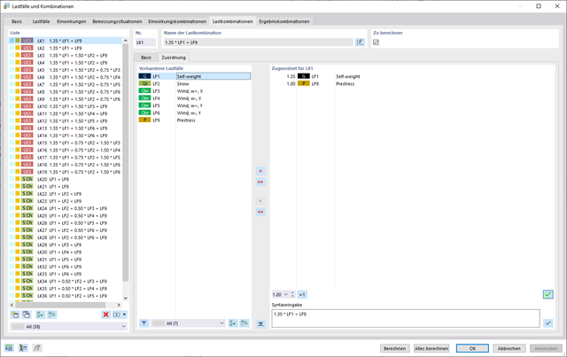
In the "Load Cases & Combinations" dialog box, you have an option to automatically generate load and result combinations as soon as you have selected the corresponding combination expressions. For example, you can also copy or add load cases in a clearly arranged window.
Furthermore, you can manage the load cases and combinations in the tables.

You can individually define all reference lengths that need to be considered in the calculation of the deflection limit value, as well as the segments to be checked, depending on the direction. For this, define design supports at the intermediate nodes of a member and assign them to the respective direction for the deformation analysis. Thus, the segments are created where it is possible to define a precamber for each direction and segment.

You can enter the structural system and calculate the internal forces in the programs RFEM and RSTAB. You have full access to the extensive material and cross-section libraries.
Timber Design is completely integrated into the main programs. At the same time, it automatically takes into account the structure and the available calculation results. You can assign further entries for the timber design, such as effective lengths, cross-section reductions, or design parameters, to the objects to be designed. You can easily select the elements graphically using the [Select] function at many places of the program.
- Design of member ends, members, nodal supports, nodes, and surfaces
- Consideration of specified design areas
- Check of cross-section dimensions
- Design according to EN 1995-1-1 (European Timber Standard) with the respective National Annexes + DIN 1052 + DSTV DIN EN 1993-1-8 + ANSI / AWC - NDS 2015 (US Standard)
- Design of various materials, such as steel, concrete, and others
- No necessary linking to specific standards
- Extensible library including timber fasteners (SIHGA, Sherpa, WÜRTH, Simpson StrongTie, KNAPP, PITZL) and steel fasteners (standardized connections in steel building design according to EC 3, M-connect, PFEIFER, TG-Technik)
- Ultimate load capacities of timber beams by the companies STEICO and Metsä Wood available in the library
- Connection to MS Excel
- Optimization of connecting elements (the most utilized element is calculated)

The Dlubal structural analysis software does a lot of work for you. The input parameters, which are relevant for the selected standards, are suggested by the program in accordance with the rules. Furthermore, you can enter response spectra manually.
Load cases of the type Response Spectrum Analysis define the direction in which response spectra act and which eigenvalues of the structure are relevant for the analysis. In the spectral analysis settings, you can define details for the combination rules, damping (if applicable), and zero-period acceleration (ZPA).