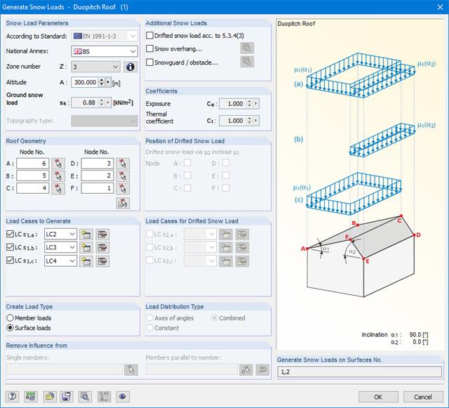
The snow load generator can generate snow loads as member loads or surface loads.
Additional snow loads such as drifted snow loads, snow overhangs, and snow guards can be taken into account as well.
The following standards are available:
-
 EN 1991-1-3 (incl. National Annexes)
 -
 DIN 1055-5
 -
 CTE DB-SE-AE
 -
 ASCE/SEI 7-16
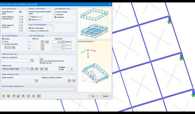
Area loads can be automatically converted into member or line loads. There are 3 options available for this:
- Generate Member Loads from Area Load via Plane
- Member loads from area loads via cells
- Line loads from surface loads on openings
In the case of member loads from area loads, a plane has to be defined via corner nodes or cells have to be selected in the graphic. The area load can either be applied to the entire surface or only the effective or projected surface of the members.
For the 'Line Loads from Area Loads on Openings' function, the corresponding openings are selected.
Online Manual RFEM | Member Loads from Area Loads via Plane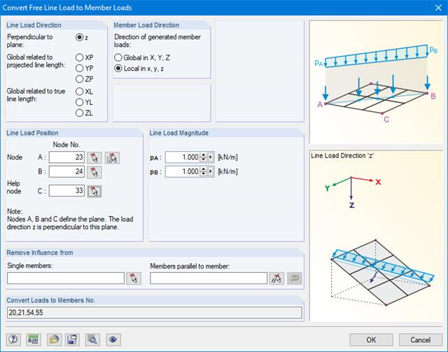
For pure member models such as grillages, you can define free line loads (e.g. from conveyor belts) and transfer them proportionally to members.
More Information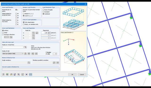
Area loads can be automatically converted into member loads. There are 2 options available for this:
- Generate Member Loads from Area Load via Plane
- Member loads from area loads via cells
Depending on the selected option, you either have to define a plane via corner nodes or select cells in the graphic. The area load can either be applied to the entire surface or only the effective or projected surface of the members.
Online Manual RFEM | Member Loads from Area Loads via Plane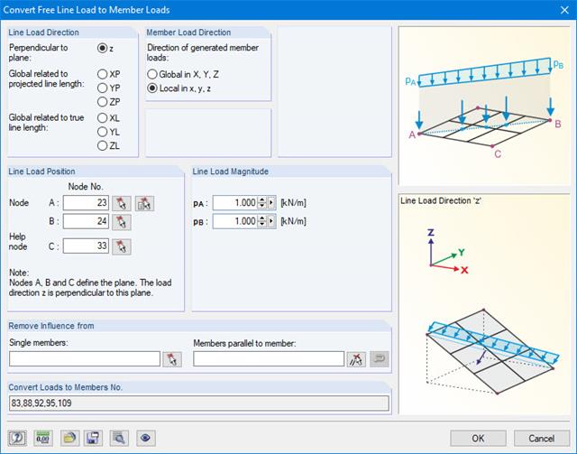
With this generator, you can e.g. for grillages, you can define free line loads (e.g. from conveyor belts) and prorate them to members.
More Information
- Simple definition of unit loads in RFEM model
- Simple definition of the points on members, surfaces, and supports to be analyzed
- Numerical results and graphical display of unit load or designed point results
- Detailed printout report, including all model and load data of each designed point and unit load used
- Design of member ends, members, nodal supports, nodes, and surfaces
- Consideration of specified design areas
- Check of cross-section dimensions
- Design according to EN 1995-1-1 (European Timber Standard) with the respective National Annexes + DIN 1052 + DSTV DIN EN 1993-1-8 + ANSI / AWC - NDS 2015 (US Standard)
- Design of various materials, such as steel, concrete, and others
- No necessary linking to specific standards
- Extensible library including timber fasteners (SIHGA, Sherpa, WÜRTH, Simpson StrongTie, KNAPP, PITZL) and steel fasteners (standardized connections in steel building design according to EC 3, M-connect, PFEIFER, TG-Technik)
- Ultimate load capacities of timber beams by the companies STEICO and Metsä Wood available in the library
- Connection to MS Excel
- Optimization of connecting elements (the most utilized element is calculated)
- Parameterized load positions of different concentrated, distributed, surface, and axle loads
- Access to a library with different axle load models
- Favorable or unfavorable load application considering influence lines and surfaces
- Summary of several moving loads in one load scheme
- Generation of a result combination for determination of the most unfavorable internal forces
- Possible to save load schemes for further use in other structures
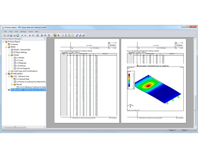
The results of each influence line and surface are listed in result windows and it is also possible to evaluate them graphically.
You can export the result tables to MS Excel. In addition, the global RFEM printout report is available for printing the input and result data as well as graphics.
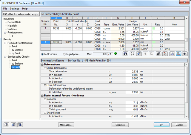
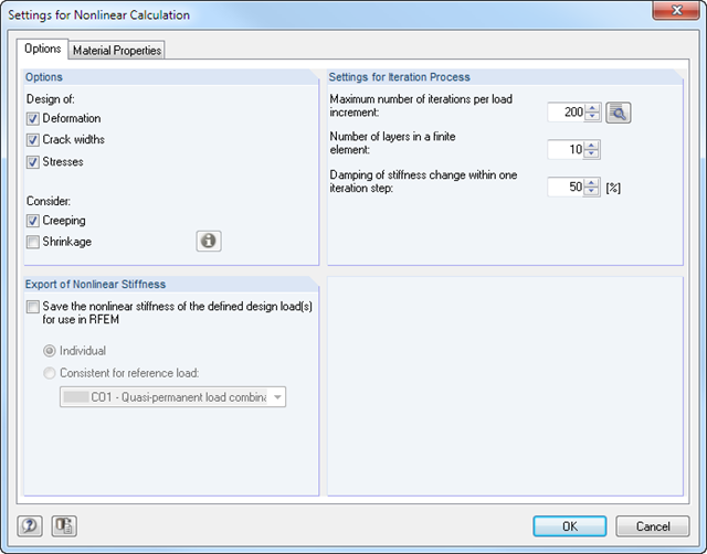
After the calculation, the module shows clearly arranged tables listing the results of the nonlinear calculation. All intermediate values are included in a comprehensible manner. Graphical representation of design ratios, deformations, concrete and reinforcing steel stresses, crack widths, crack depths, and crack spacing in RFEM facilitates a quick overview of critical or cracked areas.
Error messages or remarks concerning the calculation help you find design problems. Since the design results are displayed by surface or by point including all intermediate results, you can retrace all details of the calculation.
Due to the optional export of input or result tables to MS Excel, the data remain available for further use in other programs. The complete integration of results in the RFEM printout report guarantees verifiable structural design.
It is possible to freely model a cross-section using surfaces limited by polygonal lines, including openings and point areas (reinforcements). Alternatively, you can use the DXF interface to import the geometry. An extensive material library facilitates the modeling of composite cross-sections.
Definition of limit diameters and priorities allows for a curtailment of reinforcements. In addition, you can consider the respective concrete covers and prestresses.
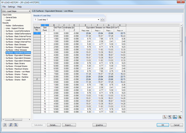
After the calculation, you can evaluate the results of the individual load steps directly in the module windows or graphically in a structural model.
The results include, for example, deformations, stresses, and internal forces of surfaces, as well as deformations and stresses of solids. It is possible to export the result combinations for each load step to RFEM. You can use these enveloping combinations for further designs in the other RFEM add-on modules.
All input data and results of the add-on module are part of the global RFEM printout report.
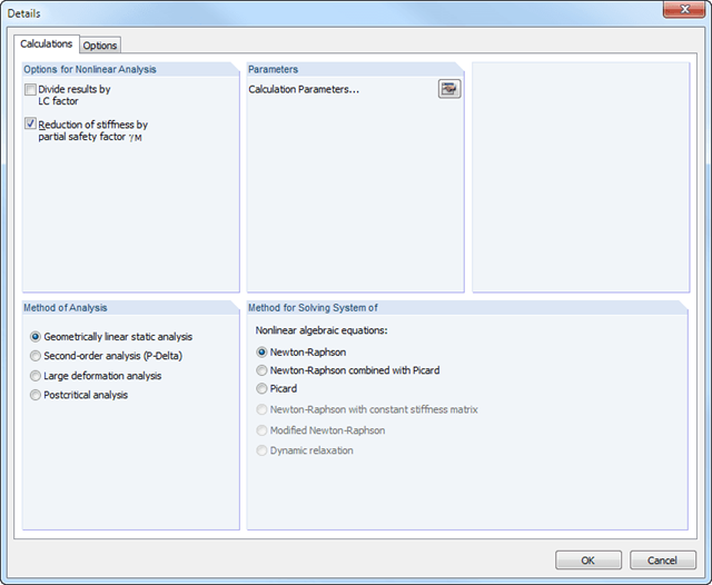
The calculation is performed successively for each load step. Permanent (plastic) deformations of previous load steps are considered when calculating further load steps. This way, it is also possible to perform a calculation with a structure relief.
The loads of the individual steps are added up (depending on the signs) throughout the calculation process. You can freely select the method of analysis (linear static, second-order, large deformation, and postcritical analysis). Furthermore, the module manages the global calculation settings.
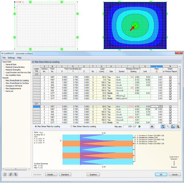
After the calculation, the maximum stresses, stress ratios, and displacements are displayed by load case, surface, or grid points. The design ratio can be related to any kind of stress type. The current location is highlighted by color in the RFEM model.
In addition to the result evaluation in tables, it is possible to display the stresses and stress ratios graphically in the RFEM work window. For this, you can adjust the colors and values assigned in the panel.
It is necessary to select load cases, load combinations, and result combinations for the ultimate and the serviceability limit state design. After selecting the surfaces to be designed, you can define the relevant material model.
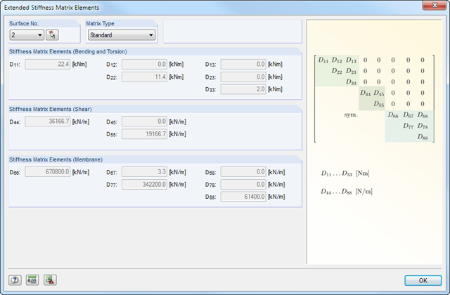
The structure of layers forming the basis for the stiffness calculation can vary. You can adjust the parameters defined by the selected material model according to your individual needs. The 3*3 matrix of the layers is modifiable as well. In this way completely free selection when generating the stiffnesses is provided.
The limit stresses of each layer are defined by the selected material. These values can be customized as well.
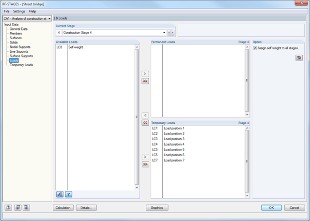
After creating the entire structure in RFEM/RSTAB, the individual structural components as well as load cases and combinations are assigned to the corresponding construction stages. For each construction stage, you can modify for example release definitions of members and supports.
Thus, it is possible to model structural modifications, such as those that occur when bridge girders are successively grouted or when columns are settled. The load cases and load combinations already created in RFEM/RSTAB are divided into "Permanent Loading" and "Temporary Loading" in the add-on module.
The defined temporary loads are superimposed by permanent loads. This way, it is possible to determine the maximum internal forces of different crane positions or to consider temporary mounting loads available only in one construction stage.
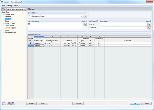
- Simple definition of construction stages in the RFEM/RSTAB structure including visualization
- Addition, removal, and modification of member, surface, and solid properties (such as member hinges, surface eccentricities, degrees of freedom for supports, and others)
- Optional superposition of construction stages with additional temporary loads; for example, mounting loads or mounting cranes, and others
- Consideration of nonlinear effects such as failure of a tension member, elastic foundations, or nonlinear supports
- Numerical and graphical result display for individual construction stages or as an envelope (Max/Min) of all construction stages
- Detailed printout report including all structural and load data of each construction stage
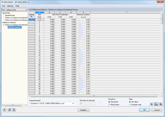
After defining the points to be analyzed, the module generates influence lines and surfaces. Then, all result diagrams are available in result windows sorted by points and unit loads applied on members, surfaces, and supports.
Member and surface models created in RFEM are analyzed at a particular point by applying a unit load with the previously defined load magnitude and direction. The module determines the way the unit load affects the internal forces at the inspected point.
This simulation is represented graphically by an influence line or influence surface resulting from the load magnitude of the force or moment at the inspected model point. The graphical representation can be used for further analyses or to check the behavior of the model.
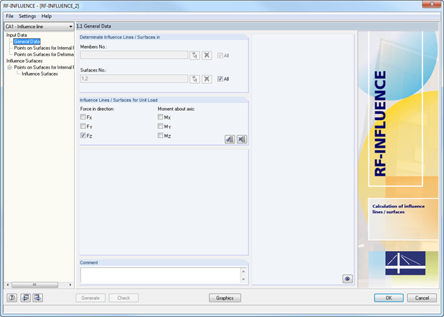
The RF-INFLUENCE add-on module determines the influence lines and surfaces of models containing beams and surfaces.
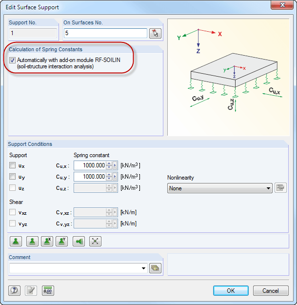
Elastic foundation coefficients are calculated according to the non-linear iterative method. The module determines elastic foundation coefficients for each individual element. They are dependent on the deformation.
- Calculation of models consisting of member, shell, and solid elements
- Import of axial forces from a load case or combination
- Non-linear stability analysis
- Optional consideration of axial forces from initial prestress
- Four equation solvers for effective calculation of various structural models
- Optional consideration of stiffness modifications in RFEM
- Calculation of buckling modes of unstable models
- Determination of stability mode greater than the user-defined load increment factor (Shift method)
- Optional determination of the mode shapes of unstable models (to identify the cause of instability)
- Visualization of stability mode
- Basis for analysis using imperfect equivalent structures in RF-IMP
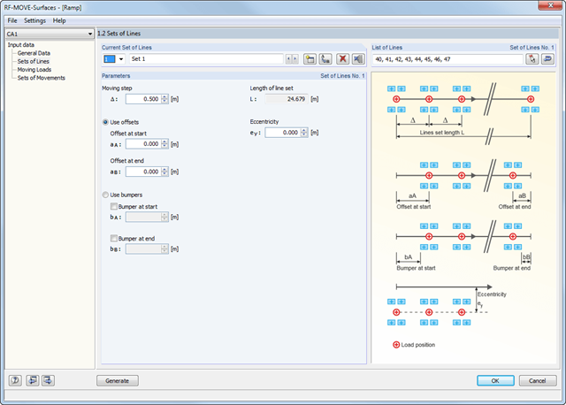
Surfaces with moving loads are selected graphically in the RFEM model. You can apply loads with several different sets of movement on one surface at the same time.
The 'lane' is defined by means of line sets. You can select them graphically in the model. In addition, you can enter the increment of the individual load steps. Several load types are available; for example, single, linear, rectangular, circular, and various axle loads. They can be applied in local and in global directions.
The different loads are summarized in load models. The module assigns defined load models to the sets of lines and creates individual load cases based on these data.
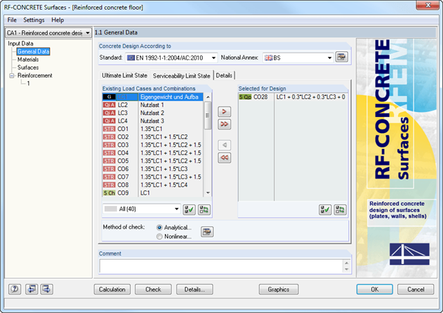
The deformation analysis with RF-CONCRETE Deflect can be activated in the settings for the analytical serviceability limit state design in the RF-CONCRETE Surfaces module. Consideration of long-term effects (creep and shrinkage) and tension stiffening between cracks can also be managed in the dialog box above. The creep coefficient and shrinkage strain are calculated using the specified input parameters or defined individually.
You can specify the deformation limit value individually for each surface or for an entire surface group. The max. deformation is defined as the allowable limit value. In addition, you have to specify whether the undeformed or the deformed system is to be used for the design check.
- Deformation analyses of reinforced concrete surfaces without or with cracks (state II) by applying the approximation method (for example, deformation analysis according to EN 1992-1-1, Cl. 7.4.3 )
- Tension stiffening of concrete applied between cracks
- Optional consideration of creep and shrinkage
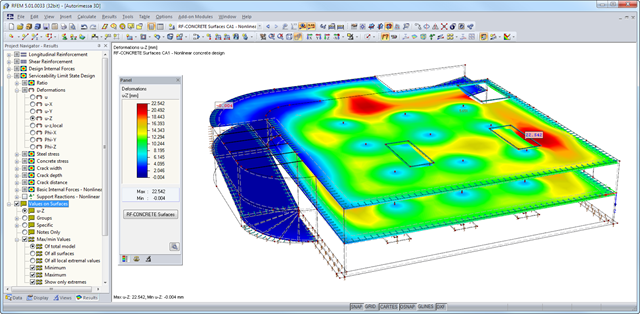
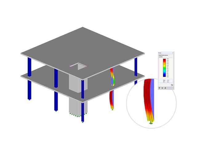
- Graphical representation of results integrated in RFEM; for example, deformation or sag of a flat slab
- Numerical results clearly arranged in tables and graphical display of the results in the model
- Complete integration of results in the RFEM printout report
- Iterative nonlinear calculation of deformations for beam and plate structures consisting of reinforced concrete by determining the respective element stiffness subjected to the defined loads
- Deformation analyses of cracked reinforced concrete surfaces (state II)
- General nonlinear stability analysis of compression members made of reinforced concrete; for example, according to EN 1992-1-1, 5.8.6
- Tension stiffening of concrete applied between cracks
- Numerous National Annexes available for the design according to Eurocode 2 (EN 1992-1-1:2004 + A1:2014, see EC2 for RFEM)
- Optional consideration of long-term influences such as creep or shrinkage
- Nonlinear calculation of stresses in reinforcing steel and concrete
- Nonlinear calculation of crack widths
- Flexibility due to detailed setting options for basis and extent of calculations
- Graphical representation of results integrated in RFEM; for example, deformation or sag of a flat slab made of reinforced concrete
- Numerical results clearly arranged in tables and graphical display of the results in the model
- Complete integration of results in the RFEM printout report
After the calculation, the module shows clearly arranged tables listing the required reinforcement and the results of the serviceability limit state design. All intermediate values are included in a comprehensible manner.
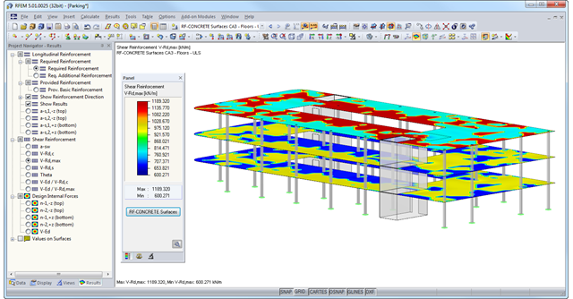
The results of RF‑CONCRETE Members are displayed as result diagrams of each member. The reinforcement proposals of the longitudinal and the shear reinforcement, including sketches, are documented in accordance with current practice. It is possible to edit the reinforcement proposal and to adjust, for example, the number of members and the anchorage. The modifications will be updated automatically. A concrete cross‑section, including reinforcement, can be visualized in a 3D rendering. This way, the program provides an optimal documentation option to create reinforcement drawings, including steel schedule.
The results of RF-CONCRETE Surfaces can be displayed graphically as isolines, isosurfaces, or numeric values. It is possible to sort the longitudinal reinforcement display by required reinforcement, required additional reinforcement, provided basic or additional reinforcement, and provided total reinforcement. The isolines of the longitudinal reinforcement can be exported as a DXF file for further use in CAD programs as a basis for reinforcement drawings.
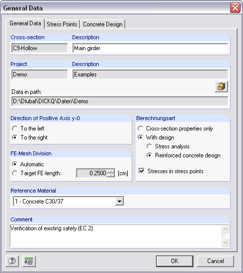
In order to facilitate the data input, surfaces, members, sets of members, materials, surface thicknesses, and cross-sections are preset in RFEM. It is possible to select the elements graphically using the [Select] function. The program provides access to the global material and section libraries. Load cases, load combinations, and result combinations can be combined in various design cases. You can enter all geometric and standard-specific reinforcement settings for the reinforced concrete design in a segmented window. The geometry entries in both RF‑CONCRETE modules differ from each other.
- In the RF-CONCRETE Members add-on module, for example, This includes, for example, specifications for the curtailment of rebars, number of layers, cutting ability of links, and anchorage type. For the fire resistance design of reinforced concrete members, you have to define the fire resistance class, the fire‑related material properties, and the cross‑section sides exposed to fire.
- In the RF‑CONCRETE Surfaces add‑on module, it is necessary to specify, for example, the concrete cover, the reinforcement direction, the minimum and the maximum reinforcement, the basic reinforcement to be applied, or the designed longitudinal reinforcement, as well as the rebar diameter.
Surfaces or members can be summarized in special "reinforcement groups", each defined by different design parameters. This way, it is possible to efficiently calculate alternative designs with different boundary conditions or modified cross‑sections.
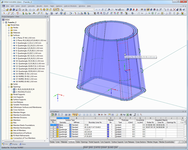
The STEP format represents a standard interface initiated by ISO (ISO 10303). In the topology specification, all shapes (line, surface, and solid models) relevant for RFEM can be transferred from CAD models.
Note: This format is completely different from the product interface DSTV (Deutscher Stahlbau Verband), which uses the same file extension *.stp.
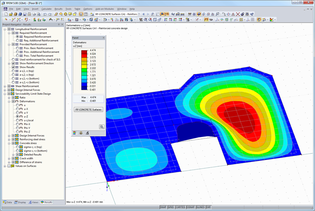
After the calculation, the module shows clearly arranged tables listing the deformation analysis results. All intermediate values are displayed in a comprehensible manner. Graphical representation of design ratios and deformation in RFEM allows a quick overview of critical areas.
Since the design results are displayed by surface or by point including all intermediate results, you can retrace all details of the calculation. The complete integration of results in the RFEM printout report guarantees verifiable structural design.
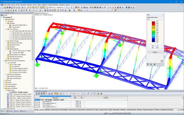
RSBUCK is distinguished by easy handling, clear data arrangement, and great user-friendliness. With only a few mouse clicks, you can define the number of buckling modes to be calculated, as well as the load case to be considered.
Structural data and boundary conditions set in the selected load case are imported automatically from RSTAB. Alternatively, you can edit the imported axial forces or enter new values manually. It is also possible to create further RSBUCK cases in order to perform several analyzes each with different boundary conditions.
For a better result display, it is possible to set the units individually in RSBUCK. If the RSTAB internal forces are not available when starting the RSBUCK module, the program calculates the required internal forces automatically before determining the buckling values.