
Get a better understanding of the stress distribution within member cross-sections using clipping planes.
.png?mw=640&hash=9de889f94dda719e52d438f3fb6a495d2dce9a98)
Use the "Independent mesh preferred" option in the FE mesh settings to create an independent FE mesh for the integrated objects.
This allows you to generate a significantly more detailed and precise FE mesh for individual objects that are integrated into one another.

Within the "Plastic capacity design | Simplex Method" in RSECTION, the simultaneous variation of shear stresses over the cross-sectional area is performed in addition to the variation of axial stresses. This extended form of analysis allows you to use redistribution reserves, especially for the cross-sections subjected to shear loading, thus loading the cross-sections even more efficiently.
Go to Explanatory Video
As soon as the program has completed the calculation, the summary of the results is listed. All result windows are integrated in the main program RFEM/RSTAB. You will find all the results arranged in tables; they can be displayed for each individual time step or as an envelope, and you also have the option of displaying the results graphically as well as animating them.
The results from the time history analysis can be displayed in the calculation diagrams. All the results are shown as a function of time. You can export the numeric values to MS Excel.
All result tables and graphics are part of the RFEM/RSTAB printout report. In this way, you can ensure clearly arranged documentation. You can also export the tables to MS Excel.

You can import STEP files into RFEM 6. The data are directly converted into the native RFEM model data.
STEP is an interface standard initiated by ISO (ISO 10303). In the geometry description, all shapes relevant for RFEM (line, surface, and solid models) can be integrated by the CAD data models.
Note: This format is not to be confused with DSTV interfaces, which also use the file extension *.stp.

In the Steel Joints add-on, you can design connections according to the American standard ANSI/AISC 360‑16. The following design procedures are integrated:
- Load and Resistance Factor Design (LRFD)
- Allowable Stress Design (ASD)
.png?mw=640&hash=55038d2a1591f62179796666cb9b2fede0274e19)
A graphical and tabular output of the results for deformations, stresses, and strains helps you when determining the soil solids. To achieve this, use the special filter criteria for targeted selection of results.
The program doesn't leave you alone with the results. If you want to graphically evaluate the results in the soil solids, you can use the guide objects. For example, you can define clipping planes. This allows you to view the corresponding results in any plane of the soil solid.
And not just that. The utilization of result sections and clipping boxes facilitates the precise graphical analysis of the soil solid.

- Calculation of deflections and comparison with the normative or manually adjusted limit values
- Consideration of a precamber for the deflection analysis
- Different limit values are possible, depending on the design situation type
- Manual Adjustment of Reference Lengths and Segmentation by Direction
- Calculation of deflections related to the initial structure or to the deformed structure
- Further detailed design checks depending on the selected design standard (for example, vibration design according to EN 1999‑1‑1, 7.2.3)
- Graphical result display integrated in RFEM/RSTAB; for example, the design ratio of a limit value, or the deformation or the sag
- Complete integration of the results into the RFEM/RSTAB printout report

You can find the serviceability limit state design checks in the result tables of the Aluminum Design add-on. They are already fully integrated there. You have the option to display the design results with all the details at each location of the designed members. You can also use graphics with the result diagrams of the design ratios.
You can integrate all result tables and graphics into the global printout report of RFEM/RSTAB as a part of the aluminum design results. RFEM/RSTAB also allows you to display and document the deformations of the entire structure independently of the add-on.

For the design according to Eurocode 9, you find the parameters of the National Annexes (NA) integrated for the following countries:
-
 DIN EN 1999-1-1/NA:2021-03 (Germany)
 -
 ÖNORM EN 1999-1-1/NA:2017-11 (Austria)
 -
 SN EN 1999-1-1/NA:2015-01 (Switzerland)
 -
 BDS EN 1999-1-1/NA:2014-05 (Bulgaria)
 -
 BS EN 1999-1-1/NA:2014-03 (United Kingdom)
 -
 CEN 1999-1-1/2013-12 (European Union)
 -
 CYS EN 1999-1-1/NA:2019-08 (Cyprus)
 -
 CZE EN 1999-1-1/NA:2015-09 (Czech Republic)
 -
 DS EN 1999-1-1/NA:2019-09 (Denmark)
 -
 ELOT EN 1999-1-1/NA:2013-12 (Greece)
 -
 EVS EN 1999-1-1/NA:2014-01 (Estonia)
 -
 HRN EN 1999-1-1/NA:2015-02 (Croatia)
 -
 I S. EN 1999-1-1/NA:2015-01 (Ireland)
 -
 ILNAS EN 1999-1-1/NA:2013-12 (Luxembourg)
 -
 IST EN 1999-1-1/NA:2014-03 (Iceland)
 -
 LST EN 1999-1-1/NA:2014-03 (Lithuania)
 -
 LVS EN 1999-1-1/NA:2015-01 (Latvia)
 -
 MSZ EN 1999-1-1/NA:2014-04 (Hungary)
 -
 NBN EN 1999-1-1/NA:2014-01 (Belgium)
 -
 NEN EN 1999-1-1/NA:2014-01 (Netherlands)
 -
 NF EN 1999-1-1/NA:2016-07 (France)
 -
 NP EN 1999-1-1/NA:2014-11 (Portugal)
 -
 NS EN 1999-1-1/NA:2014-04 (Norway)
 -
 PN EN 1999-1-1/NA:2014-05 (Poland)
 -
 SFS EN 1999-1-1/NA:2018-01 (Finland)
 -
 SIST EN 1999-1-1/NA:2014-05 (Slovenia)
 -
 SR EN 1999-1-1/NA:2015-01 (Romania)
 -
 SS EN 1999-1-1/NA:2013-12 (Sweden)
 -
 STN EN 1999-1-1/NA:2014-05 (Slovakia)
 -
 TKP EN 1999-1-1/NA:2010-01 (Belarus)
 -
 UNE EN 1999-1-1/NA:2014-01 (Spain)
 -
 UNI EN 1999-1-1/NA:2014-02 (Italy)

As usual, you enter the structural system and calculate the internal forces in the programs RFEM and RSTAB. You have unlimited access to the extensive material and cross-section libraries. Did you know that you can create general cross-sections using the RSECTION program? That saves you a lot of work.
Don't be afraid of additional windows and input chaos! Aluminum Design is completely integrated into the main programs and automatically takes into account the structure and the available calculation results. You can directly assign further entries for the aluminum design, such as effective lengths, cross-section reductions, or design parameters, to the objects to be designed. You can simply and efficiently select the elements graphically using the [Select] function.

In RFEM 6, it is possible to define line welds between surfaces and to calculate the weld stresses using the Stress-Strain Analysis add-on.
The following joint types are available:
- Butt Joint
- Corner joint
- Lap Joint
- T-joint
Depending on the selected joint type, you can select the following weld types:
- Single Square
- Double Square
- Double Bevel
- Single V
- Double V
- Single U
- Double U
- Single J
- Double J
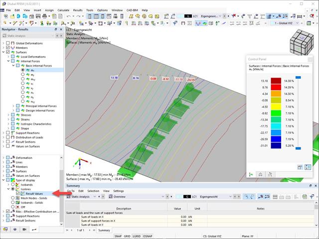
Result values for deformations, internal forces, stresses, and so on, can be displayed on the isolines.
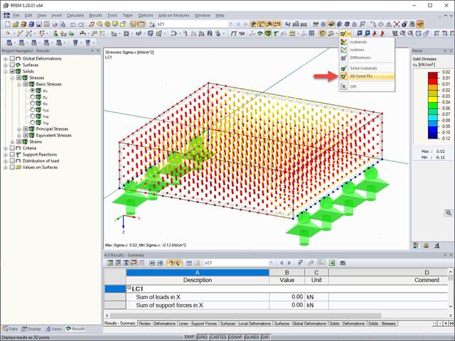
The results of solid stresses can be displayed as colored 3D points in the finite elements.

- The steel connections model and the results can be saved as a separate model file
- The resulting stresses and the results of the stability analysis (joint buckling) can be displayed in a separate model
- In the saved model, you can run a deformation animation on the connection
- Connection components are converted to surfaces and members when they are saved

- Arbitrary definition of the charring time
- Option to calculate with or without adhesion of the layer for surface structures (cross-laminated timber)
- Free user-defined specification of the fire parameters
- Consideration of Different Effective Lengths in Fire Resistance Design
- Optional design "Compression perpendicular to grain"
- Graphical result display integrated in RFEM/RSTAB, such as a design ratio
- Complete integration of the results into the RFEM/RSTAB printout report
As you probably know, the design checks for the selected members are carried out, taking into account the defined charring time. All necessary reduction factors and coefficients are stored accordingly in the program and are taken into account when determining the load-bearing capacity. That saves you a lot of work.
The effective lengths for the equivalent member design are taken directly from the strength entries. You do not have to enter them again.
After completing the design, the program presents the fire resistance design checks clearly and with all result details. This allows you to follow the results completely transparently. The results also contain all the required parameters, so you can determine the component temperature at the design time.
In addition to all these features, the program allows you to integrate all result tables and graphics, including the ultimate and serviceability limit state results,into the global printout report of RFEM/RSTAB as a part of the steel design results.

For the design according to Eurocode 5, the parameters of the National Annexes (NA) are integrated for the following countries:
-
DIN EN 1995-1-1/NA:2014-07 (Germany)
-
ÖNORM EN 1995-1-1/NA:2019-06 (Austria)
-
SN EN 1995-1-1/NA:2015-03 (Switzerland)
-
BDS EN 1995-1-1/NA:20157-06 (Bulgaria)
-
BS EN 1995-1-1/NA:2019-09 (United Kingdom)
-
CEN EN 1995-1-1/2014-05 (European Union)
-
CYS EN 1995-1-1/NA:2019-06 (Cyprus)
-
CZE EN 1995-1-1/NA:2015-05 (Czech Republic)
-
DS EN 1995-1-1/NA:2019-09 (Denmark)
-
ELOT EN 1995-1-1/NA:2010-01 (Greece)
-
EVS EN 1995-1-1/NA:2015-11 (Estonia)
-
HRN EN 1995-1-1/NA:2015-03 (Croatia)
-
I S. EN 1995-1-1/NA:2014-05 (Ireland)
-
ILNAS EN 1995-1-1/NA:2020-3 (Luxembourg)
-
IST EN 1995-1-1/NA:2014-09 (Iceland)
-
LST EN 1995-1-1/NA:2014-06 (Lithuania)
-
LVS EN 1995-1-1/NA:2014-12 (Latvia)
-
MSZ EN 1995-1-1/NA:2015-06 (Hungary)
-
NBN EN 1995-1-1/NA:2014-06 (Belgium)
-
NEN EN 1995-1-1/NA:2014-06 (Netherlands)
-
NF EN 1995-1-1/NA:2020-04 (France)
-
NP EN 1995-1-1/NA:2014-09 (Portugal)
-
NS EN 1995-1-1/NA:2014-08 (Norway)
-
PN EN 1995-1-1/NA:2014-07 (Poland)
-
SFS EN 1995-1-1/NA:2016-12 (Finland)
-
SIST EN 1995-1-1/NA:2018-01 (Slovenia)
-
SR EN 1995-1-1/NA:2014-12 (Romania)
-
 SS EN 1995-1-1/NA:2018-02 (Singapore)
 -
SS EN 1995-1-1/NA:2014-05 (Sweden)
-
STN EN 1995-1-1/NA:2019-12 (Slovakia)
-
TKP EN 1995-1-1/NA:2019-09 (Belarus)
-
UNE EN 1995-1-1/NA:2016-04 (Spain)
-
UNI EN 1995-1-1/NA:2016-11 (Italy)

Your options in timber design are diverse. You can consider cut-to-grain angles, transverse tension stresses, and volume-dependent radii of curvature for tapered and curved members. To design the area of the grain cut, the strength is adjusted accordingly in the case of bending tension or bending pressure. In order to also allow you to perform a stability analysis with the equivalent member method, the height to determine the effective and lateral-torsional buckling lengths is set at a distance of 0.65 × h to the actual design point.

You can enter the structural system and calculate the internal forces in the programs RFEM and RSTAB. You have full access to the extensive material and cross-section libraries.
Timber Design is completely integrated into the main programs. At the same time, it automatically takes into account the structure and the available calculation results. You can assign further entries for the timber design, such as effective lengths, cross-section reductions, or design parameters, to the objects to be designed. You can easily select the elements graphically using the [Select] function at many places of the program.

- Calculation of deflections and comparison with the normative or manually adjusted limit values
- Consideration of a precamber for the deflection analysis
- Different limit values are possible, depending on the design situation type
- Manual adjustment of reference lengths and segmentation by direction
- Calculation of deflections related to the initial structure or to the deformed structure
- Automatic consideration of time-dependent deformations by increasing the load with the creep factor (can also be user-defined on the stiffness side)
- Simplified vibration design
- Graphical result display integrated in RFEM/RSTAB; for example, the design ratio of a limit value, the deformation, or the sag
- Complete integration of the results into the RFEM/RSTAB printout report

You find the serviceability limit state design fully integrated in the result tables of the Timber Design add-on. If yuo want to check the design results, you can open the program and display the results with all the details at each location of the designed members. Furthermore, graphics are available for you with the result diagrams of the design ratios.
A special thing is that All result tables and graphics can be integrated into the global printout report of RFEM/RSTAB as a part of the timber design results. You can also display and document the deformations of the entire structure as a part of the RFEM/RSTAB functionality. This function is independent of the add-on.

- Calculation of deflections and comparison with the normative or manually adjusted limit values
- Consideration of a precamber for the deflection analysis
- Different limit values are possible, depending on the design situation type
- Manual adjustment of reference lengths and segmentation by direction
- Calculation of deflections related to the initial structure or to the deformed structure
- Further detailed design checks depending on the selected design standard (for example, limitation of web breathing according to EN 1993‑2)
- Graphical result display integrated in RFEM/RSTAB; for example, the design ratio of a limit value, the deformation, or the sag
- Complete integration of the results into the RFEM/RSTAB printout report

You can find the serviceability limit state design checks in the result tables of the Steel Design add-on. You can display the design results with all the details at each location of the designed members. Furthermore, graphics are available for you with the result diagrams of the design ratios. This gives you a good overview.
You can also integrate all result tables and graphics into the global printout report of RFEM/RSTAB as a part of the steel design results. Thus, you can display and document the deformations of the entire structure as a part of the RFEM/RSTAB functionality independent of the add-on.

After completing the design, the Dlubal Software presents the fire resistance design checks clearly and with all result details. This makes the results comprehensible in detail. Furthermore, the results also contain all the parameters required for the determination of the component temperature at the design time.
You can also specifically evaluate the temperature distribution in the structural component using the temperature-time diagram.
All result tables and graphics, including the ultimate and serviceability limit state results, can be integrated into the global printout report of RFEM/RSTAB as a part of the steel design results.
For the design according to Eurocode 3, the parameters of the National Annexes (NA) are integrated for the following countries:
-
DIN EN 1993-1-1/NA:2020-11 (Germany)
-
ÖNORM EN 1993-1-1/NA:2015-12 (Austria)
-
SN EN 1993-1-1/NA:2016-07 (Switzerland)
-
BDS EN 1993-1-1/NA:2015-10 (Bulgaria)
-
BS EN 1993-1-1/NA:2016-07 (United Kingdom)
-
CEN EN 1993-1-1/2015-06 (European Union)
-
CYS EN 1993-1-1/NA:2015-07 (Cyprus)
-
CZE EN 1993-1-1/NA:2016-06 (Czech Republic)
-
DS EN 1993-1-1/NA:2015-07 (Denmark)
-
ELOT EN 1993-1-1/NA:2017-01 (Greece)
-
EVS EN 1993-1-1/NA:2015-08 (Estonia)
-
HRN EN 1993-1-1/NA:2016-03 (Croatia)
-
I S. EN 1993-1-1/NA:2016-03 (Ireland)
-
ILNAS EN 1993-1-1/NA:2015-06 (Luxembourg)
-
IST EN 1993-1-1/NA:2015-11 (Iceland)
-
LST EN 1993-1-1/NA:2017-01 (Lithuania)
-
LVS EN 1993-1-1/NA:2015-10 (Latvia)
-
 MS EN 1993-1-1/NA:2010-01 (Malaysia)
 -
MSZ EN 1993-1-1/NA:2015-11 (Hungary)
-
NBN EN 1993-1-1/NA:2015-07 (Belgium)
-
NEN EN 1993-1-1/NA:2016-12 (Netherlands)
-
NF EN 1993-1-1/NA:2016-02 (France)
-
NP EN 1993-1-1/NA:2009-03 (Portugal)
-
NS EN 1993-1-1/NA:2015-09 (Norway)
-
PN EN 1993-1-1/NA:2015-08 (Poland)
-
SFS EN 1993-1-1/NA:2015-08 (Finland)
-
SIST EN 1993-1-1/NA:2016-09 (Slovenia)
-
SR EN 1993-1-1/NA:2016-04 (Romania)
-
SS EN 1993-1-1/NA:2019-05 (Singapore)
-
SS EN 1993-1-1/NA:2015-06 (Sweden)
-
STN EN 1993-1-1/NA:2015-10 (Slovakia)
-
TKP EN 1993-1-1/NA:2015-04 (Belarus)
-
UNE EN 1993-1-1/NA:2016-02 (Spain)
-
UNI EN 1993-1-1/NA:2015-08 (Italy)
.png?mw=640&hash=342149908caead326e60e26a2b5d05f7f46825cb)
Are you familiar with the Tsai-Wu material model? It combines plastic and orthotropic properties, which allows for special modeling of materials with anisotropic characteristics, such as fiber-reinforced plastics or timber.
If the material is plastified, the stresses remain constant. The redistribution is carried out according to the stiffnesses available in the individual directions. The elastic area corresponds to the Orthotropic | Linear Elastic (Solids) material model. For the plastic area, the yielding according to Tsai-Wu applies:
All strengths are defined positively. You can imagine the stress criterion as an elliptical surface within a six-dimensional space of stresses. If one of the three stress components is applied as a constant value, the surface can be projected onto a three-dimensional stress space.
If the value for fy(σ), according to the Tsai-Wu equation, plane stress condition, is smaller than 1, the stresses are in the elastic zone. The plastic area is reached as soon as fy (σ) = 1; values greater than 1 are not allowed. The model behavior is ideal-plastic, which means there is no stiffening.

Did you know? In contrast to other material models, the stress-strain diagram for this material model is not antimetric to the origin. You can use this material model to simulate the behavior of steel fiber-reinforced concrete, for example. Find detailed information about modeling steel fiber-reinforced concrete in the technical article about Determining the material properties of steel-fiber-reinforced concrete.
In this material model, the isotropic stiffness is reduced with a scalar damage parameter. This damage parameter is determined from the stress curve defined in the Diagram. The direction of the principal stresses is not taken into account. Rather, the damage occurs in the direction of the equivalent strain, which also covers the third direction perpendicular to the plane. The tension and compression area of the stress tensor is treated separately. In this case, different damage parameters apply.
The "Reference element size" controls how the strain in the crack area is scaled to the length of the element. With the default value zero, no scaling is performed. Thus, the material behavior of the steel fiber concrete is modeled realistically.
Find more information about the theoretical background of the "Isotropic Damage" material model in the technical article describing the Nonlinear Material Model Damage.
WebService and API provide you various scope of application. We have summarized some ideas as to how WebService and API can support your company:
- Creating additional applications for RFEM 6, RSTAB 9, and RSECTION 1
- Possibility to make the workflows more efficient (for example, model definition and input) and to integrate RFEM 6, RSTAB 9, and RSECTION 1 into your company applications
- Simulating and calculating several design options
- Running optimization algorithms for size, shape, and/or topology
- Accessing the calculation results
- Generation of printout reports in the PDF format
The level of quality of the work is automatically increased not only by the algorithmic model definitions, but also by:
- Extending / consolidating RFEM 6, RSTAB 9, and RSECTION 1 with your own controls
- Increased interoperability between the individual software used to complete a project
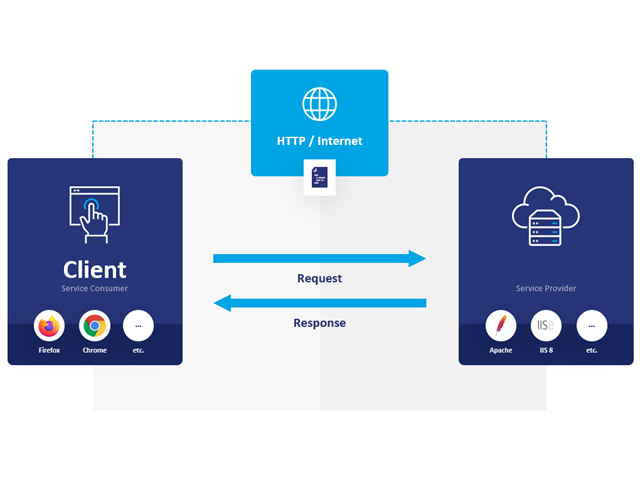
Communication is the key to success. This also applies to a client-server relation. WebService and API provides you with an XML based information exchange system for direct client-server communication. Programs, objects, messages, or documents can be integrated into these systems. For example, a web service protocol of the HTTP type runs for the client-server communication when you are looking for something in the Internet using a search engine.
Now back to Dlubal Software. In our case, the client is your programming environment (.NET, Python, JavaScript) and the service provider is RFEM 6. Client-server communication allows you to send requests to and receive feedback from RFEM, RSTAB, or RSECTION.
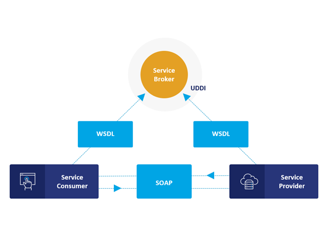
What is the difference between WebService and an API?
- WebService is a collection of open source protocols and standards used to exchange data between systems and applications. In contrast, an application programming interface (API), is a software interface through which two applications can interact without a user being involved.
- Thus, all web services are APIs, but not all APIs are web services.
What are the advantages of the WebService technology?
You can communicate more quickly within and between organizations.A service can be independent of other services.Webservice allows you to use your application to make your message or feature available to the rest of the world.Webservice helps you to exchange data between different applications and platforms Several applications can communicate, exchange data, and share services with each other. SOAP ensures that programs created on different platforms and based on different programming languages can exchange data securely.
Communication between the web service client and server is optionally encrypted via the https protocol. To do this, you can install an SSL certificate with the corresponding private key in the settings.