.png?mw=640&hash=55038d2a1591f62179796666cb9b2fede0274e19)
A graphical and tabular output of the results for deformations, stresses, and strains helps you when determining the soil solids. To achieve this, use the special filter criteria for targeted selection of results.
The program doesn't leave you alone with the results. If you want to graphically evaluate the results in the soil solids, you can use the guide objects. For example, you can define clipping planes. This allows you to view the corresponding results in any plane of the soil solid.
And not just that. The utilization of result sections and clipping boxes facilitates the precise graphical analysis of the soil solid.
You already know that it is possible to model and analyze a soil and a structure in the entire model. As a result, you have explicitly taken into account the soil-structure interaction. By modifying a component, you achieve the immediate correct consideration in the analysis as well as in the results for the entire system of the soil and structure.

Are you ready for the evaluation? Use the calculation diagrams, which show the distribution of a specific result during the calculation.
You can freely define the layout of the vertical and horizontal axes of the calculation diagram. This allows you, for example, to consider the settlement distribution of a certain node, depending on the load.

Your data are always documented in a multilingual printout report. You can adjust the content at any time and save it as a template. You can also add graphics, texts, MathML formulas, and PDF documents to your report with just a few clicks.

Enter and model a soil solid directly in RFEM. You can combine the soil material models with all common RFEM add-ons.
This allows you to easily analyze the entire models with a complete representation of the soil-structure interaction.
All parameters required for the calculation are automatically determined from the material data that you have entered. The program then generates the stress-strain curves for each FE element.

Did you know? You can enter the soil layers that you have obtained from the subsoil expertises done in the locations into the program in the form of soil samples. Assign the explored soil materials, including their material properties, to the layers.
For the definition of the samples, you can enter the data in tables as well as in the respective editing dialog box. Furthermore, you can also specify the groundwater level in the soil samples.

The soil solids that you want to analyze are summarized in soil massifs.
Use the soil samples as a basis for a definition of the respective soil massif. This way, the program allows for user-friendly generation of the massif, including the automatic determination of the layer interfaces from the sample data, as well as the groundwater level and the boundary surface supports.
Soil massifs provide you with the option to specify a target FE mesh size independently of the global setting for the rest of the structure. You can thus consider the various requirements of the building and soil in the entire model.

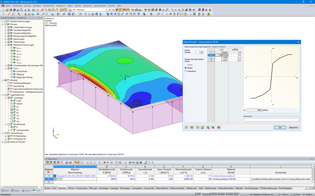
Do you want to model and analyze the behavior of a soil solid? To ensure this, special suitable material models have been implemented in RFEM.
You can use the modified Mohr-Coulomb model with a linear-elastic ideal-plastic model or a nonlinear elastic model with an oedometric stress-strain relation. The limit criterion, which describes the transition from the elastic area to that of the plastic flow, is defined according to Mohr-Coulomb.

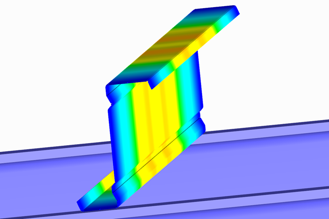
Design of a frame connection with taper and stiffened members. A stress analysis and a buckling stability analysis were carried out for the connection. To display the buckling results, the connection was converted into a separate model.
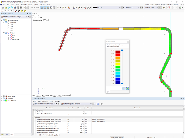
Effective Sections is an extension of the section properties program RSECTION. Compared to the RF‑/STEEL Cold-Formed Sections add-on module for RFEM 5 / RSTAB 8, the following new features have been added to Effective Sections:
- Consideration of the effects of distortional buckling of sections via eigenvalue method
- Definition of stiffeners and buckling panels no longer necessary
- Graphical display of unit stresses
- Optional manual definition of stress points

The Concrete Design add-on combines all CONCRETE add-on modules from RFEM 5 / RSTAB 8. Compared to these add-on modules, the following new features have been added to the Concrete Design add-on for RFEM 6 / RSTAB 9:
- Input of design-relevant specifications (effective lengths, durability, reinforcement directions, surface reinforcement) directly in the RFEM or RSTAB model
- Extensive input options for longitudinal and transverse reinforcement of members
- Detailed intermediate results for the design with specification of the equations of the applied standard for better traceability of the calculation
- New interaction diagram with interactive graphic for N, M, and M + N from cross-section design incl. output of the secant and tangent stiffness
- Design of the defined reinforcement in the ultimate limit state and serviceability limit state incl. graphical output of the design ratio for the respective component
- Automatic check of the defined reinforcement with regard to the construction or general reinforcement rules for reinforced member and surface components
- Cross-section design optionally with net values of the concrete section
- Design according to the Russian standard SP 63.13330

Compared to the RF‑/STEEL EC3 add-on module (RFEM 5 / RSTAB 8), the following new features have been added to the Steel Design add-on for RFEM 6 / RSTAB 9:
- In addition to Eurocode 3, other international standards are integrated (such as AISC 360, CSA S16, GB 50017, SP 16.13330)
- Consideration of hot-dip galvanizing (DASt guideline 027) in the fire protection design according to EN 1993‑1‑2
- Input option for transverse stiffeners that can be taken into account in the shear buckling analysis
- Lateral-torsional buckling can also be checked for hollow sections (for example, relevant for slender, high rectangular hollow sections)
- Automatic detection of members or member sets valid for the design (for example, automatic deactivation of members with invalid material or members already contained in a member set)
- Design settings can be adjusted individually for each member
- Graphical display of the results in the gross section or the effective section
- Output of the used design check formulas (including a reference to the used equation from the standard)

Compared to the RF‑/TIMBER Pro add-on module (RFEM 5 / RSTAB 8), the following new features have been added to the Timber Design add-on for RFEM 6 / RSTAB 9:
- In addition to Eurocode 5, other international standards are integrated (SIA 265, ANSI/AWC NDS, CSA O86, GB 50005)
- Design of compression perpendicular to grain (support pressure)
- Implementation of eigenvalue solver for determining the critical moment for lateral-torsional buckling (EC 5 only)
- Definition of different effective lengths for design at normal temperature and fire resistance design
- Evaluation of stresses via unit stresses (FEA)
- Optimized stability analyses for tapered members
- Unification of the materials for all national annexes (only one "EN" standard is now available in the material library for a better overview)
- Display of cross-section weakenings directly in the rendering
- Output of the used design check formulas (including a reference to the used equation from the standard)

Compared to the RF‑/ALUMINUM add-on module (RFEM 5 / RSTAB 8), the following new features have been added to the Aluminum Design add-on for RFEM 6 / RSTAB 9:
- In addition to Eurocode 9, the US standard ADM 2020 is integrated.
- Consideration of the stabilizing effect of purlins and sheets by rotational restraints and shear panels
- Graphical display of the results in the gross section
- Output of the used design check formulas (including a reference to the used equation from the standard)

Compared to the RF-FORM-FINDING add-on module (RFEM 5), the following new features have been added to the Form-Finding add-on for RFEM 6:
- Specification of all form-finding load boundary conditions in one load case
- Storage of form-finding results as initial state for further model analysis
- Automatic assignment of the form-finding initial state via combination wizards to all load situations of a design situation
- Additional form-finding geometry boundary conditions for members (unstressed length, maximum vertical sag, low-point vertical sag)
- Additional form-finding load boundary conditions for members (maximum force in member, minimum force in member, horizontal tension component, tension at i-end, tension at j-end, minimum tension at i-end, minimum tension at j-end)
- Material types "Fabric" and "Foil" in material library
- Parallel form-findings in one model
- Simulation of sequentially building form-finding states in connection with the Construction Stages Analysis (CSA) add-on

Compared to the RF-/STEEL Warping Torsion add-on module (RFEM 5 / RSTAB 8), the following new features have been added to the Torsional Warping (7 DOF) add-on for RFEM 6 / RSTAB 9:
- Complete integration into the environment of RFEM 6 and RSTAB 9
- 7th degree of freedom is directly taken into account in the calculation of members in RFEM/RSTAB on the entire system
- No more need to define support conditions or spring stiffnesses for calculation on the simplified equivalent system
- Combination with other add-ons is possible, for example for the calculation of critical loads for torsional buckling and lateral-torsional buckling with stability analysis
- No restriction to thin-walled steel sections (it is also possible to calculate ideal overturning moments for beams with massive timber sections, for example)

Compared to the RF‑/DYNAM Pro - Natural Vibrations add-on module (RFEM 5 / RSTAB 8), the following new features have been added to the Modal Analysis add-on for RFEM 6 / RSTAB 9:
- Preset combination coefficients for various standards (EC 8, ASCE, and so on)
- Optional neglect of masses (for example, mass of foundations)
- Methods for determining the number of mode shapes (user-defined, automatic - to reach effective modal mass factors, automatic - to reach the maximum natural frequency)
- Output of modal masses, effective modal masses, modal mass factors, and participation factors
- Masses in mesh points displayed in tables and graphics
- Various scaling options for mode shapes in the Result navigator

Compared to the RF-/DYNAM Pro - Equivalent Loads add-on module (RFEM 5 / RSTAB 8), the following new features have been added to the Response Spectrum Analysis add-on for RFEM 6 / RSTAB 9:
- Response spectra of numerous standards (EN 1998, DIN 4149, IBC 2018, and so on)
- User-defined response spectra or those generated from accelerograms
- Direction-relative response spectrum approach
- Results are stored centrally in a load case with underlying levels to ensure clarity
- Accidental torsional actions can be taken into account automatically
- Automatic combinations of seismic loads with the other load cases for use in an accidental design situation

Compared to the RF‑SOILIN add-on module (RFEM‑5), the following new features have been added to the Geotechnical Analysis add-on for RFEM 6:
- Creation of the layered soil as a 3D model from the entirety of the defined soil samples
- Recognized material law according to Mohr-Coulomb for soil simulation
- Graphical and tabular output of stresses and strains at any depth of the soil
- Optimal consideration of the soil-structure interaction on the basis of an overall model

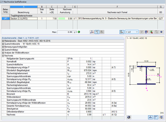
Compared to the RF‑/STEEL add-on module (RFEM 5 / RSTAB 8), the following new features have been added to the Stress-Strain Analysis add-on for RFEM 6 / RSTAB 9:
- Treatment of members, surfaces, solids, welds (line welded joints between two and three surfaces with subsequent stress design)
- Output of stresses, stress ratios, stress ranges, and strains
- Limit stress depending on the assigned material or a user-defined input
- Individual specification of the results to be calculated through freely assignable setting types
- Non-modal result details with prepared formula display and additional result display on the cross-section level of members
- Output of the design check formulas used

Compared to the RF‑/STABILITY (RFEM 5) and RSBUCK (RSTAB 8) add-on modules, the following new features have been added to the Structure Stability add-on for RFEM 6 / RSTAB 9:
- Activation as a property of a load case or a load combination
- Automated activation of the stability calculation via combination wizards for several load situations in one step
- Incremental load increase with user-defined termination criteria
- Modification of the mode shape normalization without recalculation
- Result tables with filter option

Compared to the RF‑/STAGES add-on module (RFEM 5), the following new features have been added to the Construction Stages Analysis (CSA) add-on for RFEM 6:
- Consideration of construction stages at RFEM level
- Integration of the construction stage analysis into the combinatorics in RFEM
- Additional structural elements, such as line hinges, are supported
- Analysis of alternative construction processes in a model
- Reactivation of elements
- Available for cold-formed L, Z, C, channel, top-hat, and CL sections from the cross-section database, as well as for general cold-formed (non-perforated) SHAPE-THIN-9 sections
- Determination of the effective cross-section considering the local buckling and the distortional buckling
- Cross-section ultimate limit state, stability, and serviceability limit state designs according to EN 1993‑1‑3
- Design of local transverse forces for webs without stiffening
- Available for all National Annexes included in RF-/STEEL EC3
- Module extension RF-/STEEL Warping Torsion (license required) for stability analysis according to second-order analysis as stress analysis including consideration of the 7th degree of freedom (warping)
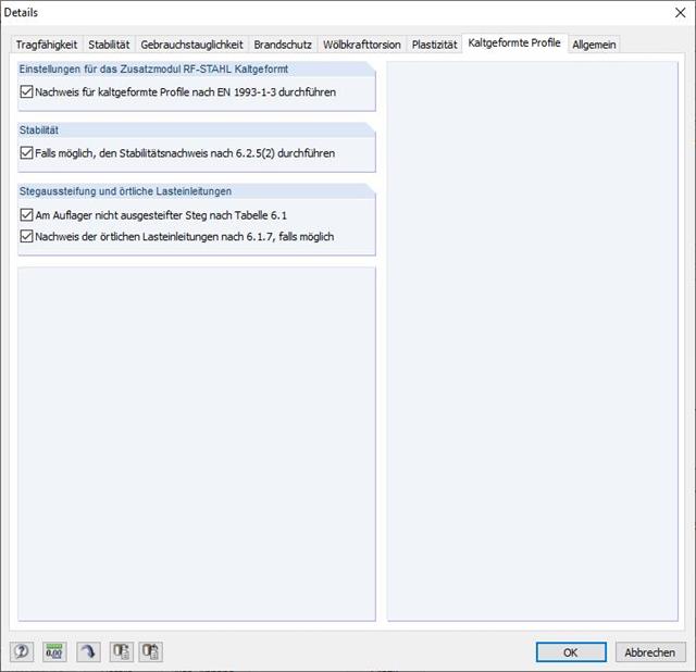
Since RF-/STEEL Cold-Formed Sections is fully integrated in RF-/STEEL EC3, the data are entered in the same way as for the usual design in this module. It is only necessary to select the design option for cold-formed cross-sections in the Details dialog box.
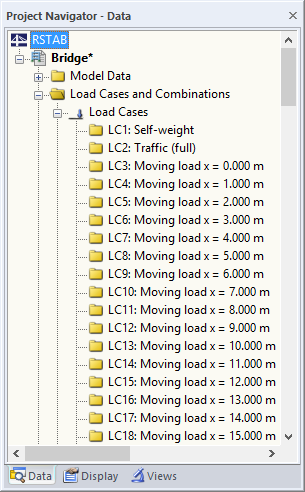
The RF-MOVE/RSMOVE add-on module does not display any result windows: You can check the created load cases, including loads, in RFEM/RSTAB. Descriptions of the individual moving loads are created on the basis of the respective load increment number.
However, it is possible to modify the descriptions in RFEM/RSTAB. You can export all data in tables to MS Excel.
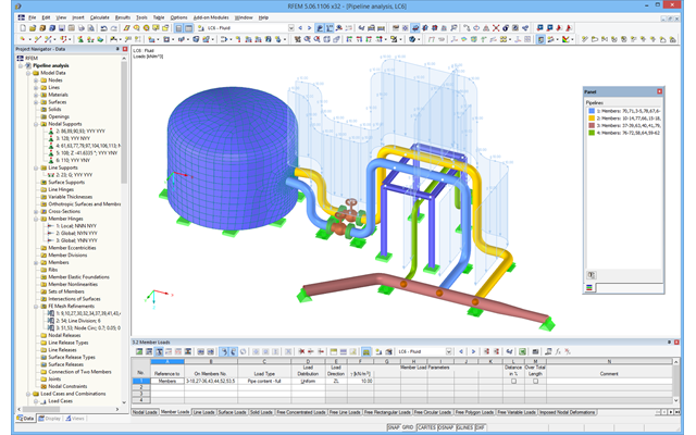
After activating the RF‑PIPING add‑on module, a new toolbar is available in RFEM and the project navigator and tables are extended. The piping system is now modeled in the same way as the members. Pipe bends are defined simultaneously by tangents (straight pipe sections) and radius. Thus, it is easy to subsequently change bend parameters.
It is also possible to extend the piping subsequently by defining special components (expansion joints, valves, and others). The implemented libraries of structural components facilitate the definition.
Continuous pipe sections are defined as sets of piping systems.
For piping loads, member loads are assigned to the respective load cases. The combination of loads is included in piping load combinations and result combinations.
After the calculation, you can display deformations, member internal forces, and support forces graphically or in tables.
Pipe stress analysis according to standards can then be performed in the RF‑PIPING Design add‑on module. You only need to select the relevant sets of piping systems and load situations.
In RFEM, there is an option to couple surfaces with the stiffness types "Membrane" and "Membrane Orthotropic" with the material models "Isotropic Nonlinear Elastic 2D/3D" and "Isotropic Plastic 2D/3D" (add-on module RF-MAT NL is required).
This functionality enables simulation of the nonlinear strain behavior of ETFE foils, for example.
In the RF-LAMINATE add-on module for RFEM, the design of torsional shear stresses in the superposition of net and gross cross-section values is possible. The design is performed separately in the x- and y-directions. The loads on the intersection points of cross-laminated timber panels are checked.
Due to the integrated RF-/STEEL Warping Torsion module extension, it is possible to perform the design according to Design Guide 9 in RF-/STEEL AISC.
The calculation is performed with 7 degrees of freedom according to the warping torsion theory and enables a realistic stability design, including consideration of torsion.
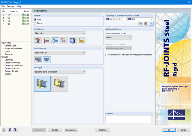
After starting the module, the joint group (rigid joints) is selected first, followed by joint category and joint type (rigid end plate connection or rigid splice plate connection). The nodes to be designed are then selected from the RFEM/RSTAB model. RF-/JOINTS Steel - Rigid automatically recognizes the joint members and determines from its location whether they are columns or beams. The user can intervene here.
If certain members are to be excluded from the calculation, they can be deactivated. Structurally similar connections can be designed for several nodes at the same time. Loads require selection of the governing load cases, load combinations, or result combinations. Alternatively, you can enter the cross‑section and load data manually. In the last input window, the connection is configured step by step.