10 Wyniki
Wyświetl wyniki:
Sortuj według:

W tym przykładzie weryfikacyjnym sprawdzana jest nośność wewnętrznego słupa płyty płaskiej na ścinanie. Słup ma przekrój kołowy o średnicy 30 cm.
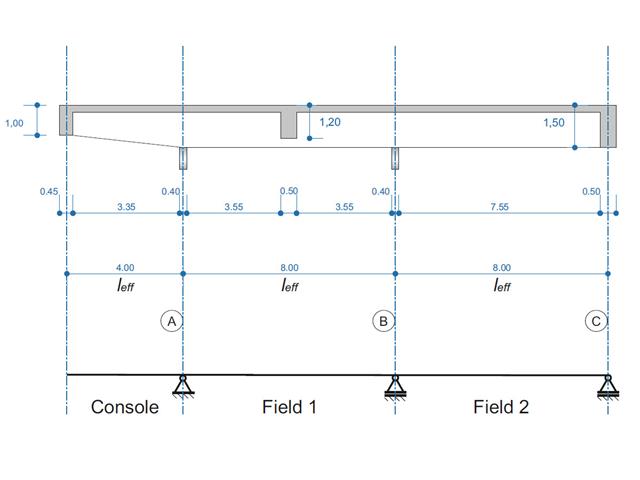
Belka żelbetowa została zaprojektowana jako belka dwuprzęsłowa na wsporniku. Przekrój zmienia się na całej długości wspornika (przekrój o zmiennym przekroju). Obliczane są siły wewnętrzne oraz wymagane zbrojenie podłużne i zbrojenie na ścinanie dla stanu granicznego nośności.
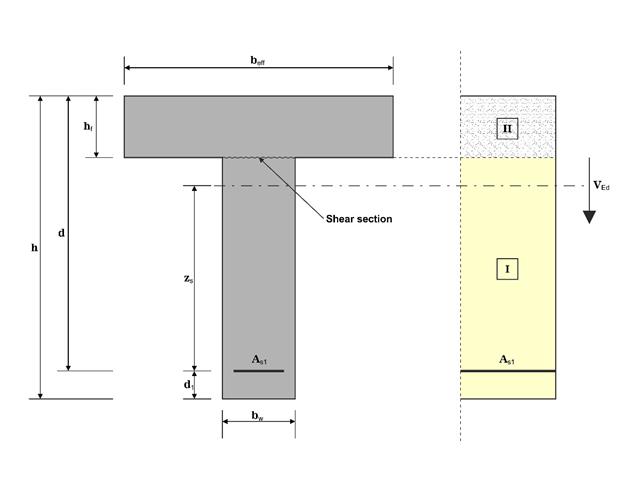
W tym przykładzie ścinanie na granicy między betonem wylanym w różnym czasie a odpowiednim zbrojeniem jest określane zgodnie z DIN EN 1992-1-1. Wyniki uzyskane w programie RFEM 6 zostaną porównane z poniższymi obliczeniami ręcznymi.
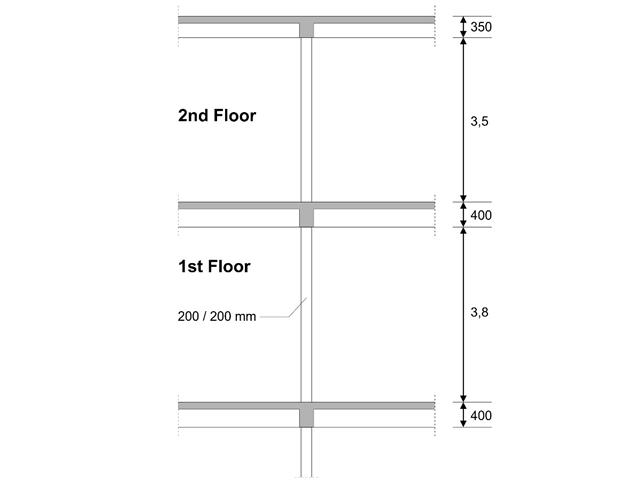
W pierwszym piętrze budynku zaprojektowano słup wewnętrzny. Słup jest monolityczny, połączony z belką górną i dolną. Uproszczona metoda A obliczeń odporności ogniowej dla słupów zgodnie z EC2-1-2 została potwierdzona, a wyniki porównane z [1].
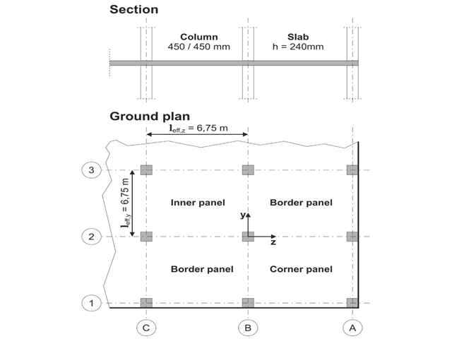
Model oparty jest na przykładzie 4 z [1]: Płyta podparta punktowo.
Należy zaprojektować płaską płytę budynku biurowego o wrażliwych na zarysowania ścianach lekkich. Należy zbadać panele wewnętrzne, brzegowe i narożne. Słupy i płyta są połączone monolitycznie. Słupy skrajne i narożne są zlicowane z krawędzią płyty. Osie słupów tworzą siatkę kwadratową. Jest to układ sztywny (budynek usztywniony ścianami usztywniającymi).
Budynek biurowy ma 5 kondygnacji i ma wysokość 3.000 m. Warunki środowiskowe, które należy przyjąć, określane są jako „zamknięte przestrzenie wewnętrzne”. Występują głównie oddziaływania statyczne.
Celem tego przykładu jest określenie momentów w płycie i wymaganego zbrojenia nad słupami przy pełnym obciążeniu.
Model oparty jest na przykładzie 4 z [1]: Płyta podparta punktowo. Siły wewnętrzne i wymagane zbrojenie podłużne można znaleźć w przykładzie weryfikacji 1022. W tym przykładzie przebijanie jest rozpatrywane w osi B/2.
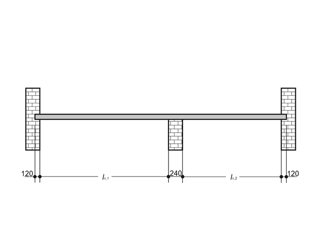
Płytę żelbetową wewnątrz budynku należy projektować jako pas o długości 1,0 m wraz z prętami. Płyta stropowa jest jednoosiowo rozpięta i przebiega przez dwa przęsła. Płyta jest mocowana do ścian murowanych za pomocą podpór swobodnie obracających się. Podpora środkowa ma szerokość 240 mm, a dwie podpory krawędziowe mają szerokość 120 mm. Oba przęsła są poddane obciążeniu użytkowemu kategorii C: obszary zborów.
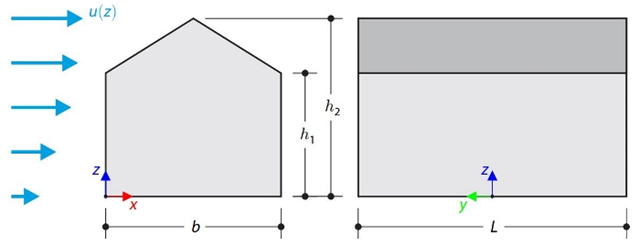
Ten przykład weryfikacyjny porównuje obliczenia obciążenia wiatrem budynku z dachem dwuspadowym, z wykorzystaniem normy ASCE 7-16, z symulacją CFD w RWIND Simulation. The building is defined according to the sketch and the inflow velocity profile taken from the ASCE 7-16 standard.
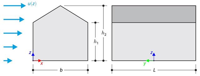
W przykładzie obliczeniowym porównano obliczenia obciążenia wiatrem budynku z dachem dwuspadowym, przeprowadzone zgodnie z normą EN 1991-1-4, z wykorzystaniem symulacji CFD w RWIND Simulation. The building is defined according to the sketch, and the inflow velocity profile is taken according to the standard EN 1991-1-4.
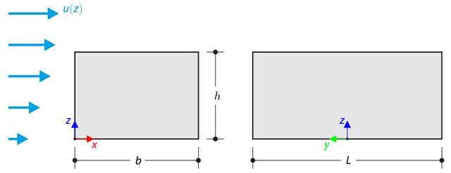
W przykładzie obliczeniowym porównano obliczenia obciążenia wiatrem budynku z płaskim dachem zgodnie z normą EN 1991-1-4 z wykorzystaniem symulacji CFD w RWIND Simulation. The building is defined according to the sketch, and the inflow velocity profile is taken according to the standard EN 1991-1-4.