10 Wyniki
Wyświetl wyniki:
Sortuj według:

Ocena przemieszczenia kondygnacji w budynku jest kluczowa dla zapewnienia zadowalających parametrów konstrukcyjnych poprzez ograniczenie przemieszczenia kondygnacji. Nadmierne znoszenie może powodować niestateczność systemu i powodować uszkodzenia elementów niekonstrukcyjnych, takich jak ściany działowe. W tym artykule opisano procedurę wyznaczania przemieszczeń międzykondygnacyjnych zgodnie z ASCE 7-22 i rozszerzeniem Model budynku w programie RFEM 6.
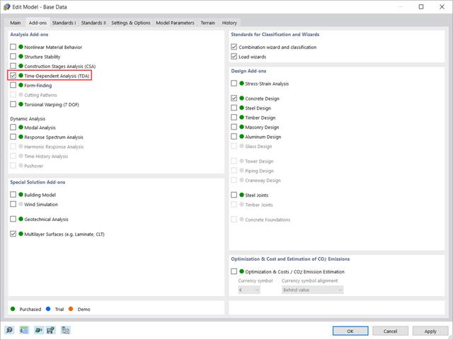
W tym artykule pokazano, w jaki sposób rozszerzenie „Analiza zależna od czasu” jest zintegrowane w programach RFEM 6 i RSTAB 9. Opisuje sposób definiowania danych wejściowych, takich jak charakterystyka materiału zależna od czasu, sposób określania typu analizy i czasy obciążenia.
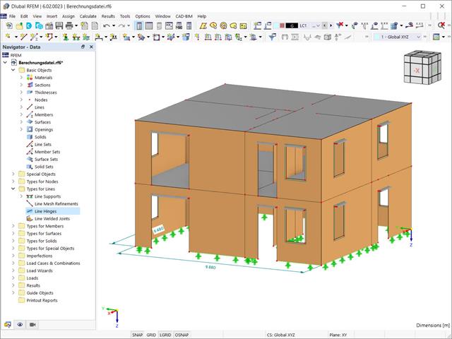
Przy użyciu specjalnego przegubu liniowego dostępnego w programie RFEM 6 można poprawnie uwzględnić podczas modelowania właściwości połączenia płyty żelbetowej ze ścianą murowaną. Z tego artykułu dowiesz się, jak zdefiniować ten typ przegubu na praktycznym przykładzie.
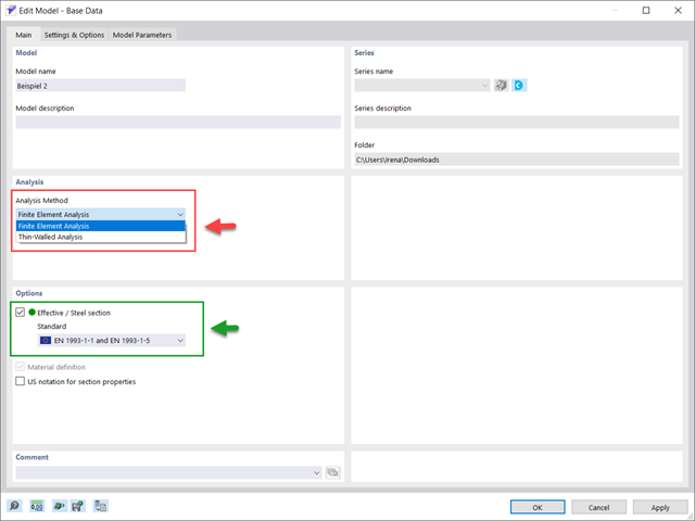
Samodzielny program RSECTION określa właściwości przekrojów cienkościennych i masywnych oraz przeprowadza analizę naprężeń. W poprzednim artykule z Bazy wiedzy zatytułowanym "Graficzne/tabelaryczne tworzenie przekrojów zdefiniowanych przez użytkownika w PRZEKRÓJ 1" omówiono podstawy definiowania przekrojów w programie. Z drugiej strony, ten artykuł jest podsumowaniem sposobu określania właściwości przekroju i przeprowadzania analizy naprężeń.

Zaletą modułu dodatkowego RFEM 6 Steel Joints jest możliwość analizy połączeń stalowych przy użyciu modelu MES, dla którego modelowanie przebiega w pełni automatycznie w tle. Elementy składowe złącza stalowego, które kontrolują modelowanie, można wprowadzić, definiując je ręcznie lub korzystając z dostępnych szablonów w bibliotece. Ta ostatnia metoda została opisana w poprzednim artykule z Bazy wiedzy zatytułowanym „Definiowanie komponentów połączenia stalowego przy użyciu biblioteki”. Definiowanie parametrów do wymiarowania połączeń stalowych jest tematem artykułu w bazie wiedzy „Projektowanie połączeń stalowych w RFEM 6”.
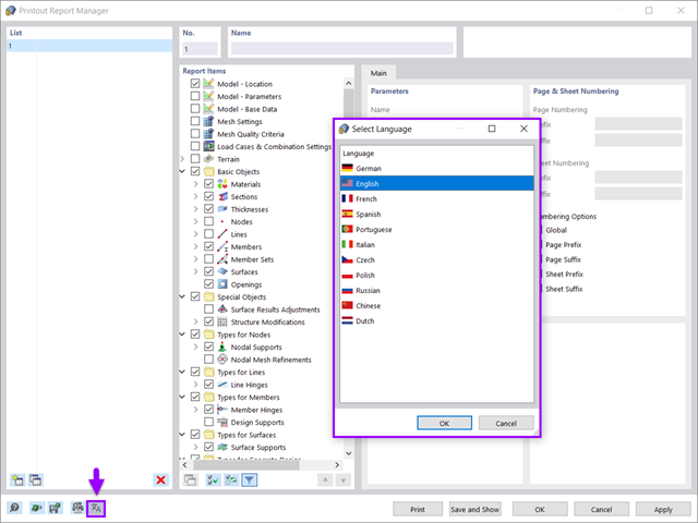
Wszystkie dane w programie RFEM 6 można udokumentować w wielojęzycznym raporcie. Protokół wydruku jest nowoczesny i zoptymalizowany w porównaniu z poprzednią generacją programu (RFEM 5). W tym artykule technicznym przedstawiono niektóre z najważniejszych funkcji.

Obliczenia konstrukcji złożonych za pomocą oprogramowania do analizy elementów skończonych są zazwyczaj przeprowadzane na całym modelu. Jednak wznoszenie tego typu konstrukcji jest procesem wieloetapowym, w którym ostateczny stan konstrukcji uzyskuje się poprzez połączenie poszczególnych elementów konstrukcyjnych. Aby uniknąć błędów w obliczeniach ogólnych modeli, należy wziąć pod uwagę wpływ procesu konstrukcyjnego. W programie RFEM 6 jest to możliwe za pomocą rozszerzenia Analiza etapów budowy (CSA).
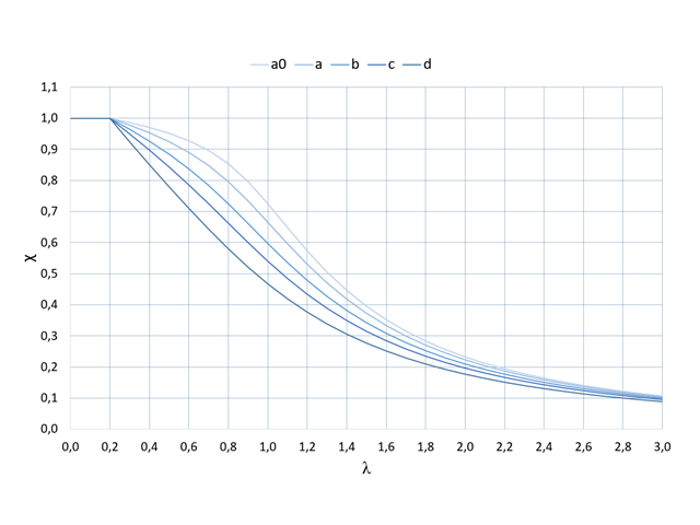
Das Zusatzmodul RF-/STAHL EC3 übernimmt die für den Biegeknicknachweis zu benutzende Knicklinie für einen Querschnitt automatisch aus den Querschnittseigenschaften. Insbesondere für allgemeine Querschnitte, aber auch für Sonderfälle, kann die Zuordnung der Knicklinie in der Moduleingabe manuell angepasst werden.
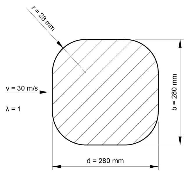
Die Windbelastung von rechteckig abgerundeten Bauteilen ist eine komplexe Angelegenheit. Równoważne siły wynikające z obciążenia wiatrem zależą od siły krążącego obciążenia wiatrem i geometrii elementu.
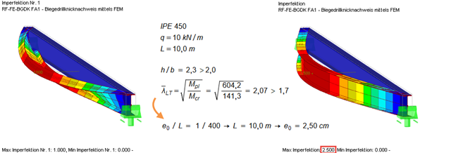
Zgodnie z normą EN 1993‑1‑1 [1] konieczne jest zastosowanie zastępczych imperfekcji geometrycznych o wartościach odzwierciedlających możliwe efekty wszystkich typów imperfekcji. In EN 1993‑1‑1 Abschnitt 5.3 werden die grundsätzlichen Imperfektionen für die Tragwerksberechnung sowie die Bauteilimperfektionen angegeben.