40 Wyniki
Wyświetl wyniki:
Sortuj według:

- 002457
- Ogólne informacje
- Projektowanie konstrukcji aluminiowych RFEM 6
- Projektowanie konstrukcji aluminiowych RSTAB 9
Rozszerzenie Projektowanie konstrukcji aluminiowych oferuje dodatkowe opcje. W tym miejscu można również obliczać przekroje ogólne, które nie są wstępnie zdefiniowane w bibliotece przekrojów. Na przykład, utwórz przekrój w programie RSECTION, a następnie zaimportuj go do RFEM/RSTAB. W zależności od zastosowanej normy projektowej dostępne są różne formaty obliczeń. Obejmuje to na przykład równoważną analizę naprężeń.
Ist zudem eine Lizenz für RSECTION und „Effektive Querschnitte“ vorhanden, so können Sie die Nachweise auch unter Berücksichtigung der effektiven Querschnittswerte nach EN 1999-1-1 führen.

- 002458
- Ogólne informacje
- Projektowanie konstrukcji aluminiowych RFEM 6
- Projektowanie konstrukcji aluminiowych RSTAB 9
Wiesz na pewno, że podczas łączenia elementów rozciąganych za pomocą połączeń śrubowych należy wziąć pod uwagę osłabienie przekroju spowodowane otworami na śruby. Programy do analizy statyczno-wytrzymałościowej również mają na to rozwiązanie. W rozszerzeniu Aluminium Design można wprowadzić lokalną redukcję przekroju pręta. Redukcję przekroju należy wprowadzić jako wartość bezwzględną lub jako procent powierzchni całkowitej.

- 002462
- Ogólne informacje
- Projektowanie konstrukcji aluminiowych RFEM 6
- Projektowanie konstrukcji aluminiowych RSTAB 9
Czy do określenia współczynnika obciążenia krytycznego w ramach analizy stateczności użyto dodatkowego solwera wewnętrznych wartości własnych? W takim przypadku można następnie wyświetlić kształt wzorca projektowanego obiektu.

- 002451
- Ogólne informacje
- Projektowanie konstrukcji aluminiowych RFEM 6
- Projektowanie konstrukcji aluminiowych RSTAB 9
- Obliczanie ugięć i porównanie z normatywnymi lub ręcznie dostosowanymi wartościami granicznymi
- Uwzględnienie wygięcia wstępnego w analizie ugięcia
- W zależności od typu sytuacji obliczeniowej możliwe są różne wartości graniczne
- Ręczne dostosowywanie długości odniesienia i segmentacji według kierunku
- Obliczenia ugięć w odniesieniu do konstrukcji wyjściowej lub konstrukcji odkształconej
- Dalsze szczegółowe weryfikacje w zależności od wybranej normy obliczeniowej (np. weryfikacja drgań zgodnie z EN 1999-1-1, 7.2.3)
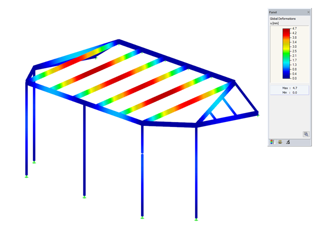
- Graficzne wyświetlanie wyników zintegrowane w programie RFEM/RSTAB, na przykład stopień wykorzystania wartości granicznej, odkształcenie lub ugięcie
- Pełna integracja wyników z raportem RFEM/RSTAB

- 002452
- Ogólne informacje
- Projektowanie konstrukcji aluminiowych RFEM 6
- Projektowanie konstrukcji aluminiowych RSTAB 9
Program wykonuje za Ciebie dużo pracy. Na przykład kombinacje obciążeń lub wyników, które są niezbędne dla stanu granicznego użytkowalności, są generowane i obliczane w programie RFEM/RSTAB. Te sytuacje obliczeniowe można wybrać w rozszerzeniu Aluminium Design w celu przeprowadzenia analizy ugięcia. W zależności od wprowadzonej przechyłki i wybranego układu odniesienia program określa obliczone wartości deformacji w każdym punkcie pręta. Następnie są one porównywane z wartościami granicznymi.
W konfiguracji Stan graniczny użytkowalności można ustawić wartość graniczną, która ma być obserwowana dla odkształcenia dla każdego komponentu z osobna. Jako dopuszczalną wartość graniczną definiuje się maksymalne odkształcenie w zależności od długości odniesienia. Definiując podpory obliczeniowe, można segmentować komponenty. W ten sposób można automatycznie określić odpowiednią długość odniesienia dla każdego kierunku obliczeń.
To nie wszystko. W oparciu o położenie przypisanych podpór obliczeniowych program automatycznie umożliwia rozróżnienie belek i belek wspornikowych. W ten sposób określana jest odpowiednio wartość graniczna.

- 002453
- Ogólne informacje
- Projektowanie konstrukcji aluminiowych RFEM 6
- Projektowanie konstrukcji aluminiowych RSTAB 9
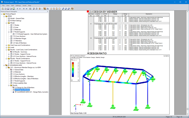
Obliczenia w stanie granicznym użytkowalności można znaleźć w tabelach wyników w rozszerzeniu do obliczeń dla aluminium. Są tam już w pełni zintegrowane. Istnieje możliwość uzyskania wyników obliczeń w każdym punkcie wymiarowanych prętów ze wszystkimi szczegółami. Można również użyć grafiki z wynikami współczynników obliczeniowych.
W razie potrzeby wszystkie tabele wyników i grafiki można uwzględnić jako część wyników obliczeń aluminium w globalnym raporcie wydruku programu RFEM/RSTAB. Program RFEM/RSTAB umożliwia również wyświetlanie i dokumentowanie wartości deformacji całej konstrukcji niezależnie od tego, czy jest to moduł dodatkowy.

- 002454
- Ogólne informacje
- Projektowanie konstrukcji aluminiowych RFEM 6
- Projektowanie konstrukcji aluminiowych RSTAB 9
Czy bardzo to lubisz? My też! Z tego powodu wszystkie sprawdzenia dotyczące normy projektowej są wyświetlane w przejrzysty sposób. Dla każdej kontroli obliczeń należy zdefiniować kryterium wykorzystania. Szczegóły obliczeń, w których wartości wejściowe, wyniki pośrednie i wyniki końcowe są uporządkowane w sposób uporządkowany, są dostępne dla każdej kontroli obliczeń. Proces obliczeń wraz ze wszystkimi wzorami, normami i wynikami znajduje się w oknie informacyjnym, w którym wyświetlane są szczegóły obliczeń.
- 002455
- Ogólne informacje
- Projektowanie konstrukcji aluminiowych RFEM 6
- Projektowanie konstrukcji aluminiowych RSTAB 9
Weryfikacje można znaleźć w rozszerzeniu dotyczącym konstrukcji aluminiowych w postaci przejrzystych tabel. Można również przedstawić graficznie rozwój współczynników obliczeniowych. Rozbudowane opcje filtrowania są dostępne zarówno w tabeli, jak i w danych wyjściowych graficznych. W ten sposób program może wyświetlać żądane obliczenia według stanu granicznego lub typu obliczeniowego.
- 002456
- Ogólne informacje
- Projektowanie konstrukcji aluminiowych RFEM 6
- Projektowanie konstrukcji aluminiowych RSTAB 9
Przy obliczaniu granicznego ugięcia należy wziąć pod uwagę określone długości odniesienia. Te długości odniesienia i sprawdzane segmenty można definiować niezależnie od siebie, w zależności od kierunku. W tym celu należy zdefiniować podpory obliczeniowe w węzłach pośrednich pręta i przypisać je do odpowiedniego kierunku dla analizy deformacji. Tworzy to segmenty, w których można uwzględnić przechyłkę dla każdego kierunku i segmentu.

- 002460
- Ogólne informacje
- Projektowanie konstrukcji aluminiowych RFEM 6
- Projektowanie konstrukcji aluminiowych RSTAB 9
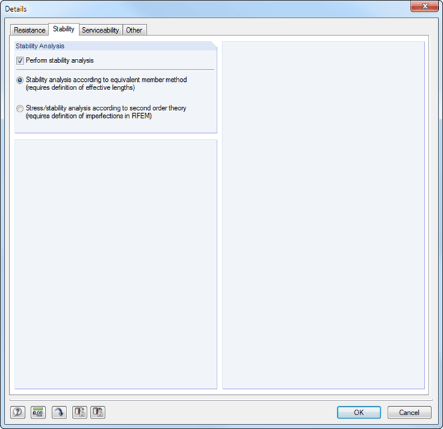
Należy upewnić się, że zdefiniowanie długości efektywnych w aluminiowym module dodatkowym jest warunkiem niezbędnym do przeprowadzenia analizy stateczności. W tym celu w oknie dialogowym należy zdefiniować podpory węzłowe i współczynniki długości efektywnej. Czy chcesz przejrzyście udokumentować podpory węzłowe i wynikające z nich segmenty wraz z powiązanym współczynnikiem długości efektywnej? W celu sprawdzenia wprowadzonych danych najlepiej jest użyć prezentacji graficznej w oknie roboczym programu RFEM/RSTAB. Oznacza to, że możesz zrozumieć projekt w dowolnym momencie i bez większego wysiłku.

- 002464
- Wyniki
- Projektowanie konstrukcji aluminiowych RFEM 6
- Projektowanie konstrukcji aluminiowych RSTAB 9
Jak zwykle, wprowadzasz układ i obliczasz siły wewnętrzne w programach RFEM i RSTAB. Masz nieograniczony dostęp do obszernych bibliotek materiałów i przekrojów. Czy wiesz, że za pomocą programu RSECTION można tworzyć przekroje ogólne? Oszczędza to dużo pracy.
Nie bój się'dodatkowych okien i chaosu przy wprowadzaniu danych! Dzieje się tak, ponieważ wymiarowanie aluminium jest w pełni zintegrowane z programami głównymi i automatycznie uwzględnia konstrukcję oraz istniejące wyniki obliczeń. Dalsze dane wejściowe dla obliczeń aluminium, takie jak długości efektywne, redukcje przekroju lub parametry obliczeniowe, można przypisać bezpośrednio do projektowanych obiektów. W wielu miejscach programu najlepiej jest użyć funkcji [Wskaż] do wyboru grafiki - w prosty i efektywny sposób.
- 002465
- Wyniki
- Projektowanie konstrukcji aluminiowych RFEM 6
- Projektowanie konstrukcji aluminiowych RSTAB 9
Czy projekt zakończył się sukcesem? Bardzo dobrze, teraz zaczyna się część zrelaksowana. Ponieważ program przedstawia przeprowadzone weryfikacje w formie tabelarycznej. Można wyświetlić szczegółowe informacje o wszystkich wynikach. Dzięki przejrzyście przedstawionym wzorom weryfikacyjnym można bez problemu zrozumieć wyniki. W oprogramowaniu Dlubal nie występuje efekt czarnej skrzynki.
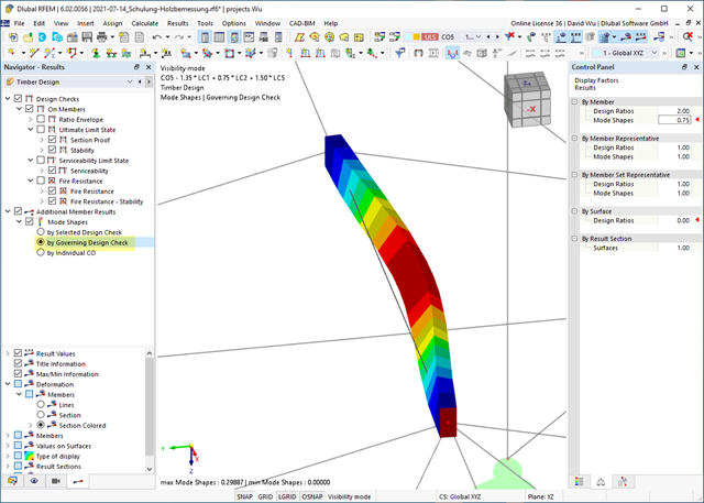
Kontrole są przeprowadzane we wszystkich istotnych punktach prętów i wyświetlane graficznie jako profil wyników. Bardziej szczegółowe grafiki można znaleźć w wynikach wyszukiwania. Obejmuje to na przykład profil naprężenia w przekroju lub kształt drgań własnych.
Wszystkie dane wejściowe i wyniki są częścią protokołu wydruku programu RFEM/RSTAB. Dla poszczególnych obliczeń można wybrać zawartość raportu i żądaną głębokość danych wyjściowych.

- 002133
- Ogólne informacje
- Projektowanie konstrukcji drewnianych RFEM 6
- Projektowanie konstrukcji drewnianych RSTAB 9
- Szeroki wybór przekrojów, takich jak przekroje prostokątne, kwadratowe, teowe, okrągłe, złożone, nieregularne przekroje parametryczne i wiele innych (przydatność do obliczeń zależy od wybranej normy)
- Wymiarowanie drewna klejonego krzyżowo (CLT)
- Wymiarowanie materiałów drewnopochodnych i drewna klejonego warstwowo zgodnie z EC 5
- Wymiarowanie prętów o zmiennym przekroju (metoda zgodna z normą)
- Możliwe jest dostosowanie istotnych współczynników obliczeniowych i parametrów normowych
- Elastyczność dzięki szczegółowym opcjom ustawień dla podstawy i zakresu obliczeń
- Szybkie i przejrzyste wyświetlanie wyników dla globalnej oceny ich rozkładu na konstrukcji po zakończeniu obliczeń
- Szczegółowe wyniki obliczeń i niezbędne wzory (jasna i łatwa do zweryfikowania ścieżka wyników)
- Przejrzyste zestawienie wyników w formie numerycznej w stosownych oknach oraz możliwość ich graficznego przedstawienia na konstrukcji
- Integracja wyników z protokołem wydruku programu RFEM/RSTAB

- 002372
- Ogólne informacje
- Projektowanie konstrukcji drewnianych RFEM 6
- Projektowanie konstrukcji drewnianych RSTAB 9
- Dowolna definicja czasu zwęglania
- W przypadku konstrukcji powierzchniowych (drewno klejone krzyżowo) można obliczyć z przyczepnością lub bez
- Bezpłatna, zdefiniowana przez użytkownika specyfikacja parametrów pożaru
- Uwzględnienie różnych długości efektywnych do obliczania odporności ogniowej
- Opcjonalne obliczenia dla 'ściskania w poprzek włókien'
- Zintegrowane z RFEM/RSTAB graficzne wyświetlanie wyników, np. B. Stopień wykorzystania
- Pełna integracja wyników z protokołem wydruku programu RFEM/RSTAB
- 002385
- Ogólne informacje
- Projektowanie konstrukcji drewnianych RFEM 6
- Projektowanie konstrukcji drewnianych RSTAB 9
Czy do określenia współczynnika obciążenia krytycznego w ramach analizy stateczności użyto solwera wartości własnych rozszerzenia? W takim przypadku można wyświetlić decydujący kształt drgań własnych projektowanego obiektu. W tym miejscu dostępny jest solwer wartości własnych do analizy zwichrzenia, w zależności od zastosowanej normy obliczeniowej.
- 002387
- Obliczenia
- Projektowanie konstrukcji drewnianych RFEM 6
- Projektowanie konstrukcji drewnianych RSTAB 9
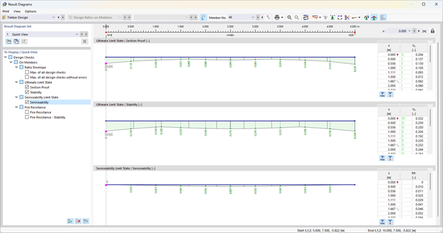
Jeśli projekt się powiedzie, nadejdzie czas. Ponieważ program wykonuje za Ciebie wiele procesów. Przeprowadzone kontrole obliczeń są na przykład wyświetlane w tabeli. Tutaj wyświetlane są wszystkie szczegóły wyników. Dzięki przejrzyście przedstawionym wzorom obliczeniowym wyniki są bezproblemowe i zrozumiałe. Nie ma tu efektu "czarnej skrzynki".
Obliczenia są przeprowadzane we wszystkich decydujących miejscach prętów i przedstawiane graficznie w postaci wykresu wyników. Ponadto w wynikach dostępne są szczegółowe grafiki, takie jak rozkład naprężeń w przekroju lub decydujący kształt postaci drgań.
Wszystkie dane wejściowe i wyniki są częścią protokołu wydruku programu RFEM/RSTAB. Zawartość protokołu i jego zakres można wybrać specjalnie dla poszczególnych warunków projektowych.

- 002140
- Ogólne informacje
- Projektowanie konstrukcji aluminiowych RFEM 6
- Projektowanie konstrukcji aluminiowych RSTAB 9
- Szeroki wybór dostępnych przekrojów, takich jak dwuteowniki walcowane; ceowniki; teowniki; kątowniki; profile zamknięte prostokątne i okrągłe; pręty okrągłe; przekroje symetryczne i niesymetryczne, parametryczne przekroje dwuteowe, teowe, kątowniki; przekroje złożone (przydatność do obliczeń zależy od wybranej normy)
- Wymiarowanie ogólnych przekrojów RSECTION (w zależności od formatów obliczeniowych dostępnych w odpowiedniej normie); na przykład obliczanie naprężeń zastępczych
- Wymiarowanie prętów o zbieżnym przekroju (metoda zależna od normy)
- Możliwe jest dostosowanie istotnych współczynników obliczeniowych i parametrów normowych
- Elastyczność dzięki szczegółowym opcjom ustawień dla podstawy i zakresu obliczeń
- Szybkie i przejrzyste wyświetlanie wyników dla globalnej oceny ich rozkładu na konstrukcji po zakończeniu obliczeń
- Szczegółowe wyniki obliczeń i niezbędne wzory (jasna i łatwa do zweryfikowania ścieżka wyników)
- Przejrzyste zestawienie wyników w formie numerycznej w stosownych oknach oraz możliwość ich graficznego przedstawienia na konstrukcji
- Integracja wyników z protokołem wydruku programu RFEM/RSTAB

- 002141
- Ogólne informacje
- Projektowanie konstrukcji aluminiowych RFEM 6
- Projektowanie konstrukcji aluminiowych RSTAB 9
- Wymiarowanie elementów rozciąganych, ściskanych, zginanych, ścinanych, skręcanych i poddanych połączonemu działaniu tych sił wewnętrznych
- Obliczanie rozciągania z uwzględnieniem zredukowanej powierzchni przekroju (np. osłabienie z uwagi na otwory)
- Automatyczna klasyfikacja przekrojów w celu sprawdzenia wyboczenia lokalnego
- Siły wewnętrzne z obliczeń ze skręcaniem skrępowanym (7 stopni swobody) są uwzględniane w kontroli naprężeń zastępczych (obecnie nie dla normy ADM 2020)
- Wymiarowanie przekrojów klasy 4 o właściwościach przekroju efektywnego zgodnie z EN 1999-1-1 (dla przekrojów RSECTION wymagane są licencje dla przekrojów RSECTION i "Przekroje efektywne")
- Sprawdzenie wyboczenia przy ścinaniu z uwzględnieniem usztywnień poprzecznych
- 002142
- Wyniki
- Projektowanie konstrukcji aluminiowych RFEM 6
- Projektowanie konstrukcji aluminiowych RSTAB 9
- Analiza stateczności dla wyboczenia giętnego, wyboczenia skrętnego i wyboczenia giętno-skrętnego przy ściskaniu
- Analiza zwichrzenia elementów poddanych obciążeniu momentem
- Import długości efektywnych z obliczeń przy użyciu rozszerzenia Stateczność konstrukcji
- Graficzne wprowadzanie i kontrola zdefiniowanych podpór węzłowych oraz długości efektywnych w celu analizy stateczności
- W zależności od normy istnieje wybór między wprowadzaniem wartości Mcr przez użytkownika, metodą analityczną z normy lub wykorzystaniem wewnętrznego solwera wartości własnych
- Uwzględnienie panelu usztywniającego i ograniczenia obrotu podczas korzystania z solwera wartości własnych
- Graficzne przedstawienie postaci własnej w przypadku zastosowania solwera wartości własnych
- Analiza stateczności elementów konstrukcyjnych ze ściskaniem i naprężeniem zginającym, w zależności od normy obliczeniowej
- Przejrzyste obliczanie wszystkich niezbędnych współczynników, takich jak współczynniki interakcji
- Alternatywne uwzględnienie wszystkich wpływów dla analizy stateczności podczas określania sił wewnętrznych w programie RFEM/RSTAB (analiza drugiego rzędu, imperfekcje, redukcja sztywności, ewentualnie w połączeniu z rozszerzeniem Skręcanie skrępowane (7 stopni swobody))
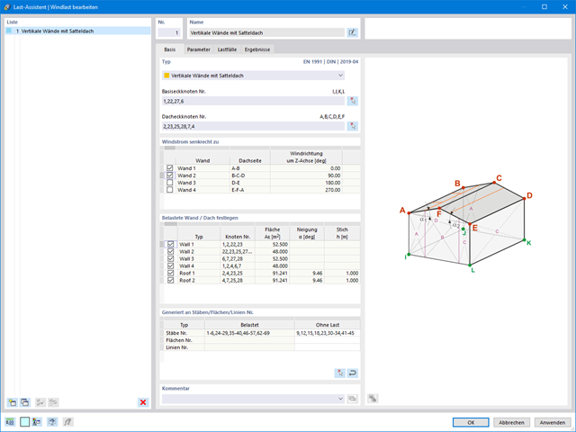
Obciążenia wiatrem również nie stanowią problemu w obliczeniach. Obciążenia wiatrem mogą być generowane automatycznie jako obciążenia prętowe lub obciążenia powierzchniowe (RFEM) na następujących elementach konstrukcyjnych:
- Ściany pionowe
- Dachy płaskie
- Dachy jednospadowe
- Dachy dwuspadowe/korytowe
- Ściany pionowe z dachem dwuspadowym
- Ściany pionowe z dachem płaskim/jednospadowym
Dostępne są następujące normy:
-
 EN 1991-1-4 (wraz z załącznikami krajowymi)
 -
 ASCE 7
 -
 NBC
NBC -
 CTE DB-SE-AE
 -
 GB 50009

Dzięki oprogramowaniu Dlubal można bezpiecznie i łatwo planować konstrukcje na całym świecie. Wybierz jedną z wielu norm w Danych ogólnych. Można również zdecydować, czy kombinacje mają być tworzone automatycznie.
Dostępne są poniższe normy:
-
EN 1990
-
EN 1990 | Drewno
-
EN 1990 | Mosty drogowe
-
EN 1990 | Suwnice
-
EN 1990 | Geotechnika
-
EN 1990 | Podstawa + drewno
-
EN 15512
-
ASCE 7
-
ASCE 7 | Drewno
-
ACI 318
-
IBC
-
CAN/CSA
-
NBC
-
NBC | Drewno
-
 NBR 8681
 -
 IS 800
 -
 SIA 260
 -
SIA 260 | Drewno
-
 BS 5950
 -
GB 55001 | GB 55002
-
GB 50009 | GB 50011
-
GB 50068 | GB 50011
-
CTE DB-SE
-
 SANS 10160-1
 -
 NTC
NTC -
NTC | Drewno
-
 AS/NZS 1170.0
 -
 SP 20.13330:2016
 -
 TSC | Stal
W przypadku norm europejskich (EC) dostępne są następujące załączniki krajowe:
-
 DIN | 2012-08 (Niemcy)
 -
CEN | 2010-04 (Unia Europejska)
-
 BDS | 2013-03 (Bułgaria)
 -
BS | 2009-06 (Wielka Brytania)
-
 ČSN | 2015-05 (Republika Czeska)
 -
 CYS | 2010-06 (Cypr)
 -
 DK | 2013-09 (Dania)
 -
 ELOT | 2009-01 (Grecja)
 -
 EVS-EN 1990:2002+NA:2002 (Estonia)
 -
 IS | 2010-04 (Irlandia)
 -
 LST | 2012-01 (Litwa)
 -
 LU | 2020-03 (Luksemburg)
 -
 LVS | 2015-01 (Łotwa)
 -
 MS | 2010-02 (Malezja)
 -
 NBN | 2015-05 (Belgia)
 -
 NEN | 2011-12 (Holandia)
 -
 NF | 2011-12 (Francja)
 -
 NP | 2009-12 (Portugalia)
 -
 NS | 2016-05 (Norwegia)
 -
 ÖNORM | 2013-03 (Austria)
 -
 PN | 2010-09 (Polska)
 -
 SFS | 2010-09 (Finlandia)
 -
 SIST | 2010-08 (Słowenia)
 -
 SR | 2006-10 (Rumunia)
 -
 SS | 2008-06 (Singapur)
 -
 SS | 2019-01 (Szwecja)
 -
 STN | 2010-01 (Słowacja)
 -
 TKP | 2011-11 (Białoruś)
 -
UNE | 2010-07 (Hiszpania)
-
 UNI | 2010-10 (Włochy)
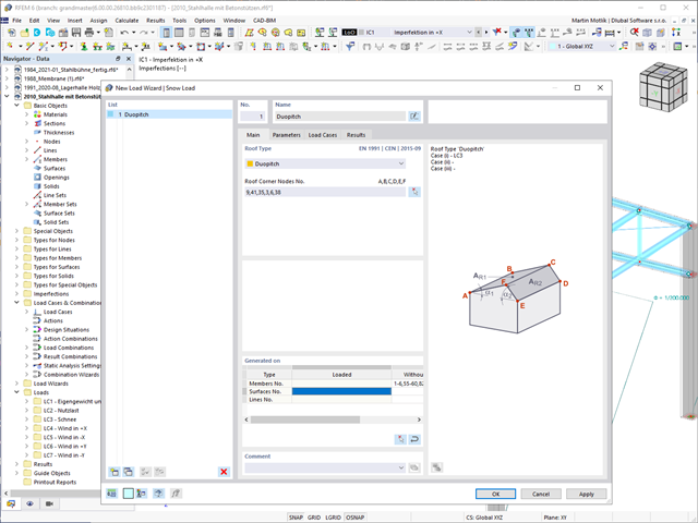
Czy Twoje konstrukcje również muszą wytrzymać opady śniegu? Za pomocą Kreatora obciążeń śniegiem można generować obciążenia śniegiem jako obciążenia prętowe lub powierzchniowe.
Dostępne są poniższe normy:
-
EN 1991-1-3 (wraz z załącznikami krajowymi)
-
ASCE 7
-
NBC
-
SIA 261
-
CTE DB-SE-AE
-
GB 50009
-
IS 875
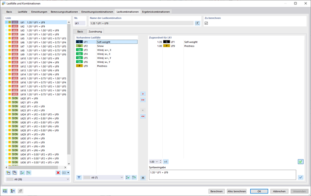
W oknie dialogowym "Przypadki obciążeń i kombinacje" istnieje możliwość automatycznego generowania kombinacji obciążeń i wyników po wybraniu odpowiednich reguł kombinacji. W przejrzyście zorganizowanym oknie można na przykład kopiować lub dodawać przypadki obciążeń.
Dodatkowo w tabelach można zarządzać przypadkami i kombinacjami obciążeń.
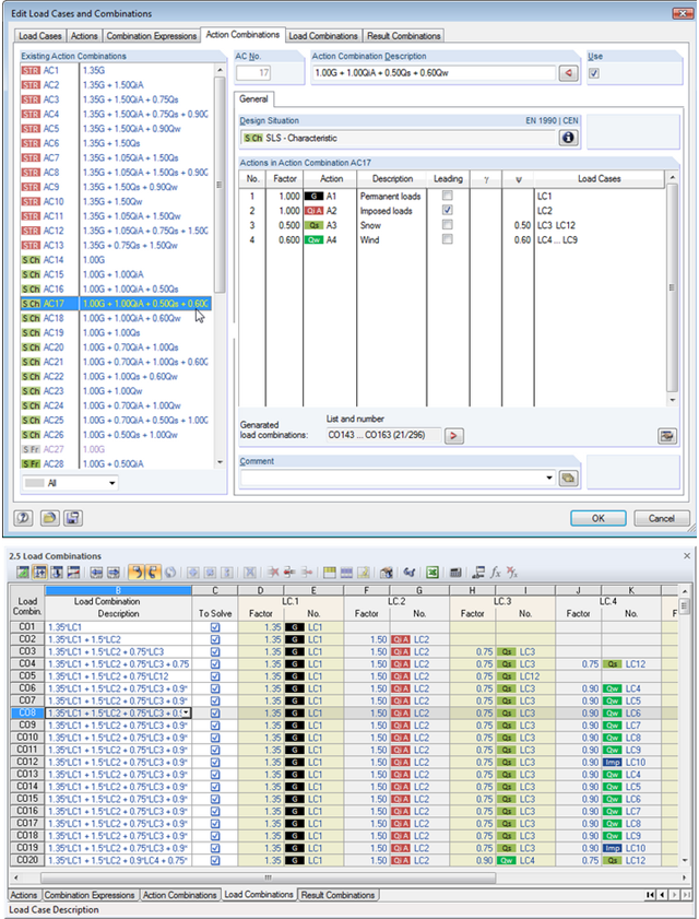
W ten sposób można wykorzystać wszystkie opcje dostępne w oknie dialogowym 'Edytować przypadki obciążeń i kombinacje', aby ułatwić sobie pracę. Po wybraniu odpowiednich reguł kombinacji można tutaj automatycznie tworzyć kombinacje obciążeń i wyników. W tym przejrzystym oknie dialogowym można np. kopiować, dodawać lub przenumerować przypadki obciążeń.
Dodatkowo należy sprawdzić przypadki i kombinacje obciążeń w tabelach 2.1 - 2.6.
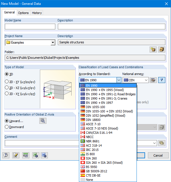
Okno dialogowe Dane podstawowe zawiera szeroką gamę norm oraz opcję automatycznego tworzenia kombinacji. Dostępne są poniższe normy:
-
EN 1990:2002
-
EN 1990 + EN 1995:2004 (Drewno)
-
EN 1990 + EN 1991-2; Mosty drogowe
-
EN 1990 + EN 1991-3; Dźwigi
-
EN 1990 + EN 1997
-
wg DIN 1055-100:2001-03
-
DIN 1055-100 + DIN 1052:2004-08 (drewno)
-
DIN 1055-100 + DIN 18008 (Glass)
-
DIN 1052 (uproszczony) (drewno)
-
DIN 18800:1990
-
ASCE 7-10
-
ASCE 7-10 NDS (Drewno)
-
ACI 318-14
-
IBC 2015
-
CAN/CSA S 16.1-94:1994
-
NBCC: 2005
-
NBR 8681
-
IS 800:2007
-
SIA 260:2003
-
SIA 260 + SIA 265:2003 (drewno)
-
BS 5950-1:2000
-
GB 50009-2012
-
CTE DB-SE
W przypadku norm europejskich (EC) dostępne są następujące załączniki krajowe:
-
DIN EN 1990/NA:2009-05 (Niemcy)
-
NBN EN 1990 - ANB: 2005 (Belgia)
-
BDS EN 1990:2003/NA:2008 (Bułgaria)
-
DK EN 1990/NA:2007-07 (Dania)
-
SFS EN 1990/NA:2005 (Finlandia)
-
NF EN 1990/NA:2005/12 (Francja)
-
ELOT EN 1990:2009 (Grecja)
-
UNI EN 1990/NA:2007-07 (Włochy)
-
IS EN 1990:2002 + NA:2010 (Irlandia)
-
LVS EN 1990:2003/NA:2010 (Łotwa)
-
LST EN 1990/NA:2010-11 (Litwa)
-
LU EN 1990/NA:2011-09 (Luksemburg)
-
MS EN 1990:2010 (Malezja)
-
NEN EN 1990/NA:2006 (Holandia)
- NS EN 1990/NA:2008 (Norwegia)
-
ÖNORM EN 1990:2007-02 (Austria)
-
NP EN 1990:2009 (Portugalia)
-
PN EN 1990/NA:2004 (Polska)
-
SR EN 1990/NA:2006-10 (Rumunia)
-
SIST EN 1990: 2004/A1:2005 (Słowenia)
-
SS EN 1990:2008 (Singapur)
-
SS EN 1990/BFS 2010:28 (Szwecja)
-
STN EN 1990/NA:2009-08 (Słowacja)
-
UNE EN 1990 2003 (Hiszpania)
-
CSN EN 1990/NA:2004-03 (Republika Czeska)
-
BS EN 1990/NA:2004-12 (Wielka Brytania)
-
TKP EN 1990/NA:2011 (Białoruś)
-
CYS EN 1990:2002 (Cypr)
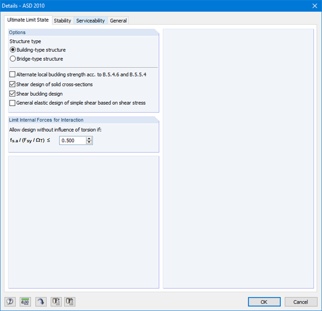
Najpierw należy zdecydować, czy obliczenia mają być przeprowadzone zgodnie z ASD czy LRFD. Następnie można wprowadzić przypadki obciążeń, kombinacje obciążeń i kombinacje wyników, które mają zostać obliczone. Kombinacje obciążeń zgodnie z ASCE 7 można generować ręcznie lub automatycznie w programie RFEM/RSTAB.
Dalsze specyfikacje obejmują wstępne ustawienie bocznych podpór pośrednich, długości efektywnych i innych parametrów obliczeniowych specyficznych dla normy. W przypadku stosowania prętów ciągłych w każdym węźle pośrednim poszczególnych prętów można zdefiniować indywidualne warunki podparcia i mimośrody. Następnie specjalne narzędzie do analizy statyczno-wytrzymałościowej określa wewnętrznie efektywne promienie bezwładności wymagane do analizy stateczności w takich sytuacjach.
- Wymiarowanie prętów i zbiorów prętów dla rozciągania, ściskania, zginania, ścinania, skręcania oraz kombinacji sił wewnętrznych
- Analiza stateczności dla wyboczenia i zwichrzenia
- Automatyczne określanie efektywnego promienia bezwładności przez specjalne zintegrowane oprogramowanie (analiza wartości własnych) dla ogólnych warunków obciążenia i podparcia
- Alternatywne obliczenia analityczne efektywnego promienia bezwładności w sytuacjach standardowych
- Możliwość zastosowania oddzielnych podpór bocznych do belek
- Definicja podpór węzłowych dla zbiorów prętów
- Obliczenia w stanie granicznym użytkowalności (ugięcie)
- Optymalizacja przekroju
- Szeroki wybór dostępnych przekrojów, takich jak dwuteowniki walcowane, ceowniki, teowniki, kątowniki, profile zamknięte prostokątne i okrągłe, pręty okrągłe i wiele innych.
- Szczegółowa dokumentacja wyników wraz z odniesieniami do równań obliczeniowych z zastosowanej normy
- Różne opcje filtrowania i sortowania wyników, w tym listy wyników według prętów, przekrojów i położenia x lub według przypadków, kombinacji obciążeń i kombinacji wyników
- Tabela wyników dla smukłości pręta i głównych sił wewnętrznych
- Jednostki metryczne i anglosaskie
Pierwsza tabela wyników pokazuje maksymalne stopnie wykorzystania wraz z odpowiednim wykorzystaniem dla każdego obliczanego przypadku, grupy i kombinacji obciążeń.
Kolejne tabele pokazują wszystkie szczegółowe wyniki posegregowane według określonych kryteriów w rozwijanych elementach menu. Oprócz tego można wyświetlać wszystkie wyniki pośrednie dla każdego miejsca wzdłuż długości pręta. W ten sposób można łatwo prześledzić, jak w module zostały przeprowadzone poszczególne obliczenia.
Pełne dane z modułu stanowią część protokołu wydruku programu RFEM/RSTAB.
Obliczenia nośności przekroju obejmują analizę rozciągania i ściskania wzdłuż włókien, zginania, zginania i rozciągania/ściskania oraz wytrzymałości na ścinanie.
Elementy konstrukcyjne z możliwością wyboczenia i zwichrzenia są analizowane według metody pręta zastępczego i uwzględniane są systematyczne ściskanie osiowe, zginanie z lub bez siły ściskającej oraz zginanie i rozciąganie. Ugięcie wewnętrznych przęseł i wsporników jest porównywane z maksymalnym dopuszczalnym ugięciem.
Oddzielne przypadki obliczeniowe umożliwiają elastyczną analizę stateczności prętów, zbiorów prętów i obciążeń.
Parametry istotne dla obliczeń, takie jak analiza stateczności, czas trwania obciążenia w warunkach pożaru, smukłość prętów i ugięcie graniczne, można dostosowywać zgodnie z potrzebami.
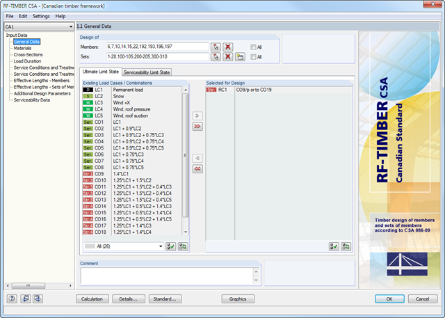
Po otwarciu modułu należy wybrać pręty/zbiory prętów, przypadki obciążeń, kombinacje obciążeń lub kombinacje wyników dla obliczeń stanu granicznego nośności i użytkowalności. Materiały z programu RFEM/RSTAB są wstępnie ustawione i można je dostosować w RF-/TIMBER CSA. Charakterystyki materiałowe zgodne z odpowiednimi normami zapisane są w bibliotece.
Podczas sprawdzania przekrojów można określić, czy uwzględniany jest przekrój wybrany w programie RFEM/RSTAB, czy przekrój zmodyfikowany. Następnie można zdefiniować klasy trwania obciążenia, warunki wilgotnościowe oraz obróbkę drewna.
Do analizy deformacji wymagane są długości referencyjne odpowiednich prętów i zbiorów prętów. Ponadto można zdefiniować określony kierunek ugięcia, wygięcie wstępne i typ belki.
W przypadku obliczeń odporności ogniowej można zdefiniować strony zwęglenia pręta lub zbioru prętów.