We provide hints and tips to help you get started with the basic program RFEM.
Home Support & Learning Learning Videos Webinar: Time-History Analysis in RFEM - Induced Vibrations (USA)
Webinar: Time-History Analysis in RFEM - Induced Vibrations (USA)
Video
First Steps with RFEM
Description
Content:
- Overview and features of RFEM and the dynamic add-on modules
- Natural frequency analysis utilizing RF-DYNAM Pro - Natural Vibrations
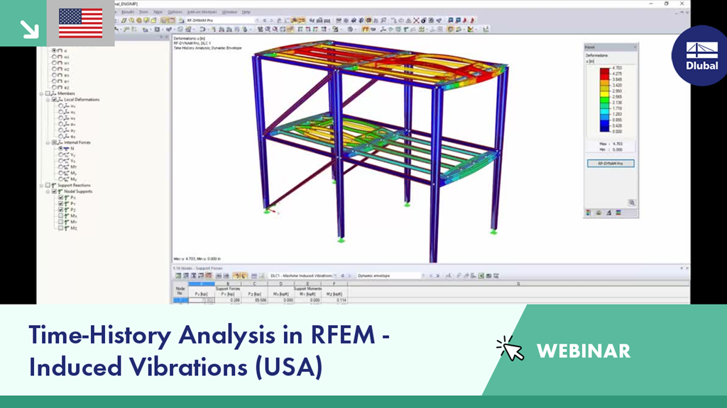
- Time-history analysis utilizing RF-DYNAM Pro - Forced Vibrations
- Example 1: Machine induced vibrations
- Example 2: Blast analysis
Time Schedule:
00:00 min: Introduction
01:08 min: Concept of RFEM and RF-DYNAM Pro modules
04:16 min: RF-DYNAM Pro – Forced Vibrations overview
09:14 min: Example 1: Machine-Induced Vibrations introduction
13:24 min: RF-DYNAM Pro – Natural Vibrations analysis
23:12 min: RF-DYNAM Pro – Forced Vibrations machine-induced time-history analysis
37:11 min: Review of machine-induced time-history results
43:37 min: Time-history analysis with modified structure
53:05 min: Example 2: Blast Analysis introduction
58:34 min: RF-DYNAM Pro – Forced Vibrations blast time-history analysis
1:01:47 : Review of blast time-history results
1:03:36 : Integration of dynamic results with design modules
1:06:20 : Closing remarks
Keywords
Dlubal Webinar Induced Vibrations Time History Time History Analysis Vibrations Structural Analysis Structural Analysis Software Dynamic Dynamic Analysis Design EC Eurocode Eurocodes BIM Building Information Modeling CAD FEA FEM Finite Elements Webinar about Dlubal Software Webinar Dlubal Tutorial
Links
Contact us
Do you have any questions about our products or need advice on selecting the products needed for your projects?
Contact us via our free e-mail, chat, or forum support or find various suggested solutions and useful tips on our FAQ page.
Recommended Events
Eurocode 5 | Timber structures according to EN 1995-1-1
Online Training 03/17/2021 8:30 AM - 12:30 PM CET
Eurocode 3 | Steel structures according to DIN EN 1993-1-1
Online Training 03/18/2021 8:30 AM - 12:30 PM CET
Eurocode 3 | Steel structures according to DIN EN 1993-1-1
Online Training 05/06/2021 8:30 AM - 12:30 PM
Eurocode 2 | Concrete structures according to DIN EN 1992-1-1
Online Training 05/11/2021 8:30 AM - 12:30 PM
Eurocode 5 | Timber structures according to DIN EN 1995-1-1
Online Training 05/20/2021 8:30 AM - 12:30 PM
RFEM | Structural dynamics and earthquake design according to EC 8
Online Training 06/02/2021 8:30 AM - 12:30 PM
Videos
Models to Download
Knowledge Base Articles
New
Manual adjustment of the buckling curve according to EN 1993-1-1
The RF-/STEEL EC3 add-on module automatically transfers the buckling line to be used for the flexural buckling analysis for a cross-section from the cross-section properties. In particular for general cross -sections, but also for special cases, the assignment of the buckling line can be adjusted manually in the module input.
Screenshots
Product Features Articles

SHAPE-THIN | Cold-Formed Sections
SHAPE-THIN determines the effective cross-sections according to EN 1993-1-3 and EN 1993-1-5 for cold-formed sections. You can optionally check the geometric conditions for the applicability of the standard specified in EN 1993‑1‑3, Section 5.2.
The effects of local plate buckling are considered according to the method of reduced widths and the possible buckling of stiffeners (instability) is considered for stiffened sections according to EN 1993-1-3, Section 5.5.
As an option, you can perform an iterative calculation to optimize the effective cross-section.
You can display the effective cross-sections graphically.
Read more about designing cold-formed sections with SHAPE-THIN and RF-/STEEL Cold-Formed Sections in this technical article: Design of a Thin-Walled, Cold-Formed C-Section According to EN 1993-1-3.
Frequently Asked Questions (FAQ)
- Why do I get high differences when designing a longitudinally stiffened buckling panel compared to the German and Austrian National Annexes?
- How can I create a curved or curved section?
- How can I perform the stability analysis for an edgewise supported flat steel, for example 100/5, in RF-/STEEL EC3? Although the cross-section is rotated by 90 ° in RFEM/RSTAB, it is displayed lying flat in RF-/STEEL EC3.
- How are the signs to be interpreted for the release results of the line release and line hinges?
- How are hot -dip galvanized components considered for fire protection in the Steel EC 3 add -on module?
- How is the rotational stiffness of a buckling stiffener determined in FE-BUCKLING?
- In RF-/STEEL EC3, is the "Elastic design (also for cross-section class 1 and 2)" option under "Details → Ultimate Limit State" considered for the stability analysis when activated?
- How can I get the member end forces to design the connections?
- I would like to calculate and design "temporary structures." What do I need for this?
- How can I create a drilled beam in RFEM?
Customer Projects