First of all, the effective surfaces of the single panels are determined using the reduction factor according to EN 1993‑1‑5 [1], Section 4.4 to take into account the buckling of single panels. In the second step, the buckling safety of the entire panel is determined while taking into account buckling behavior similar to one of the buckling members. With the reduction factor of the entire panel buckling, the effective widths of the single panels are reduced again. This results in an effective cross-section that can be handled as belonging to Cross-Section Class 3.
Example
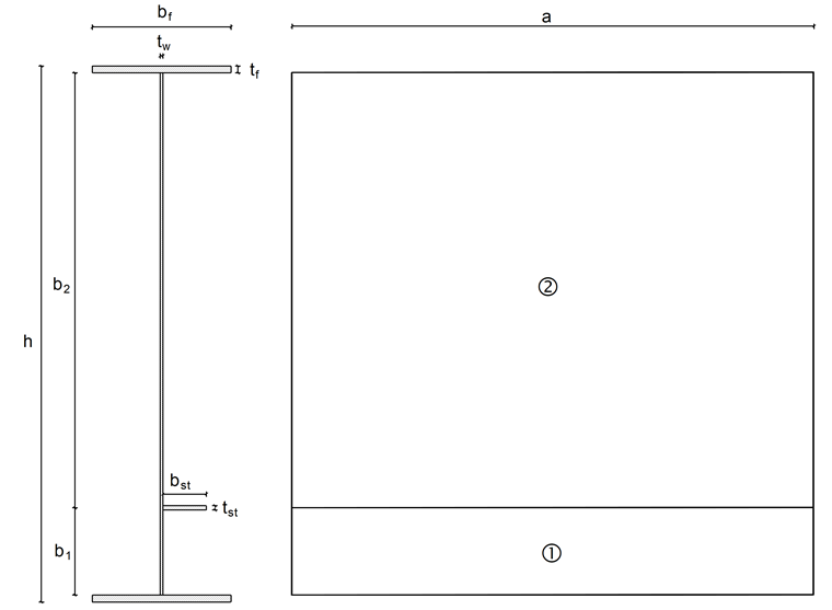
The following example is taken from the Steel Structures Yearbook 2015 [2]. The cross-section consists of an I-beam of which the web is stiffened by rigid transverse stiffeners and a longitudinal stiffener. The transverse stiffeners are arranged at a distance of 3,000 mm to one another and the longitudinal stiffener is welded at a distance of 500 mm from the bottom flange. The welds are neglected. A compression axial force of NEd = 4,000 kN acts.
Material:
S355 J0
fy = 35.5 kN/cm² (for t ≤ 3 mm and t ≤ 16 mm)
fy = 34.5 kN/cm² (for t >16 mm and t ≤ 40 mm)
E = 21,000 kN/cm²
G = 8,076.92 kN/cm²
γM0 = 1.0
a = 3,000 mm
b1 = 500 mm
b2 = 2,500 mm
bf = 800 mm
bst = 250 mm
tw = 15 mm
tf = 40 mm
tst = 25 mm
h = 3,080 mm
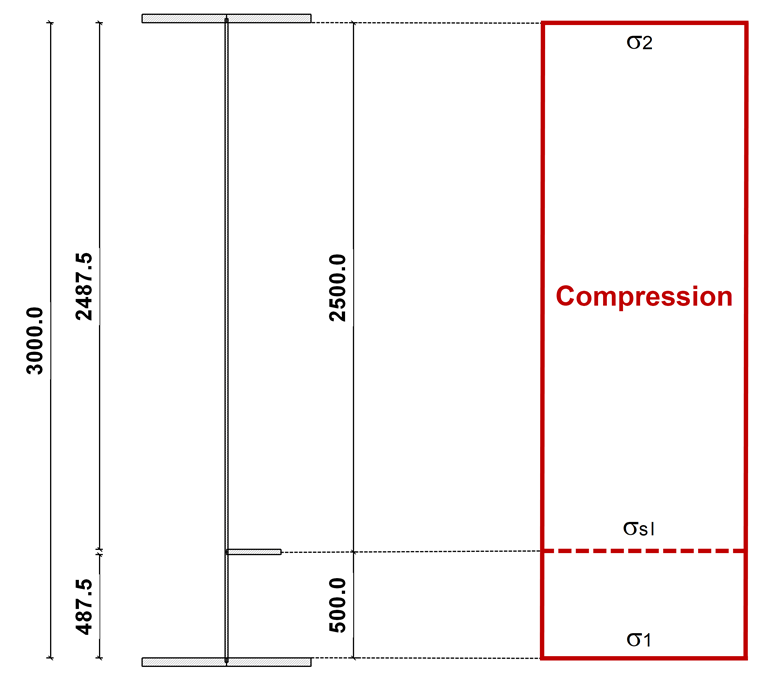
Gross Cross-Section and Stress Distribution
The stress is calculated as follows:
The gross cross-section and the stress distribution are shown in Image 02.
Cross-Section Classification
During a cross-section classification, an evaluation is performed to ascertain if a buckling design is necessary for the single panels. If the single panel is at least Cross-Section Class 3, local buckling does not govern.
Flange
The maximum c/t ratio λi is determined according to EN 1993‑1‑1 [3], Table 5.2.
The flange has to be assigned to Cross-Section Class 3. Local buckling thus does not govern and no reduction of the single panels of the flange is necessary.
Web
The maximum c/t ratio λi is determined according to [3], Table 5.2.
The Single Panel 1 has to be assigned to Cross-Section Class 3. Local buckling thus does not govern, and no reduction of the single panels of the flange is necessary.
The maximum c/t ratio λi is determined according to [3], Table 5.2.
The Single Panel 2 has to be assigned to Cross-Section Class 4. Local buckling thus governs for this single panel and a reduction of this single panel is necessary.
Stiffener
The maximum c/t ratio λi is determined according to [3], Table 5.2.
The web has to be assigned to Cross-Section Class 3. Local buckling thus does not govern and no reduction of this single panel is necessary.
Effective Widths
Single Panel 1 is assigned to Cross-Section Class 3 so that local buckling does not govern. The effective cross-section values correspond to the gross cross-section values. According to [1], Table 4.1, this results in the following effective widths:
Single Panel 2 is assigned to Cross-Section Class 4 so that local buckling does not govern. The effective widths of the Single Panel 2 have to be determined according to [1], Section 4.4.
The stress distribution in the Single Panel 2 is uniform. This results in a stress ratio of ψ = 1 and, according to Table 4.1, in a buckling value of kσ = 4.0. According to [1], Section 4.4(2), the result for the slenderness ratio λp2 is:
The local reduction factor ρ is determined according to [1], Equation (4.2):
The effective widths of Single Panel 2, taking into account the local buckling, are calculated according to [1], Table 4.1:
The widths of the gross cross-section result in:
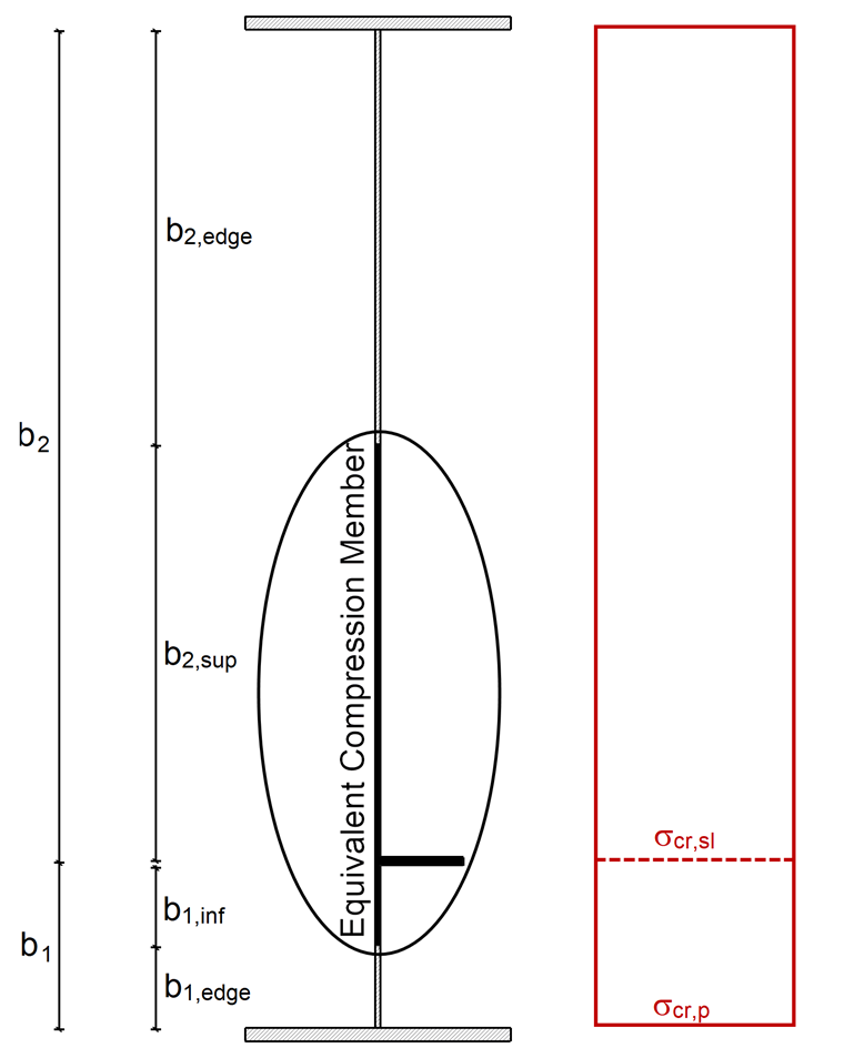
Slab-Like Behavior
The elastic critical buckling stress of the stiffness σcr,sl is calculated according to [1], Annex A.2.2. The effective length of the stiffness ac has to be calculated first:
The elastic critical buckling stress of the stiffness σcr,sl results in a < ac in:
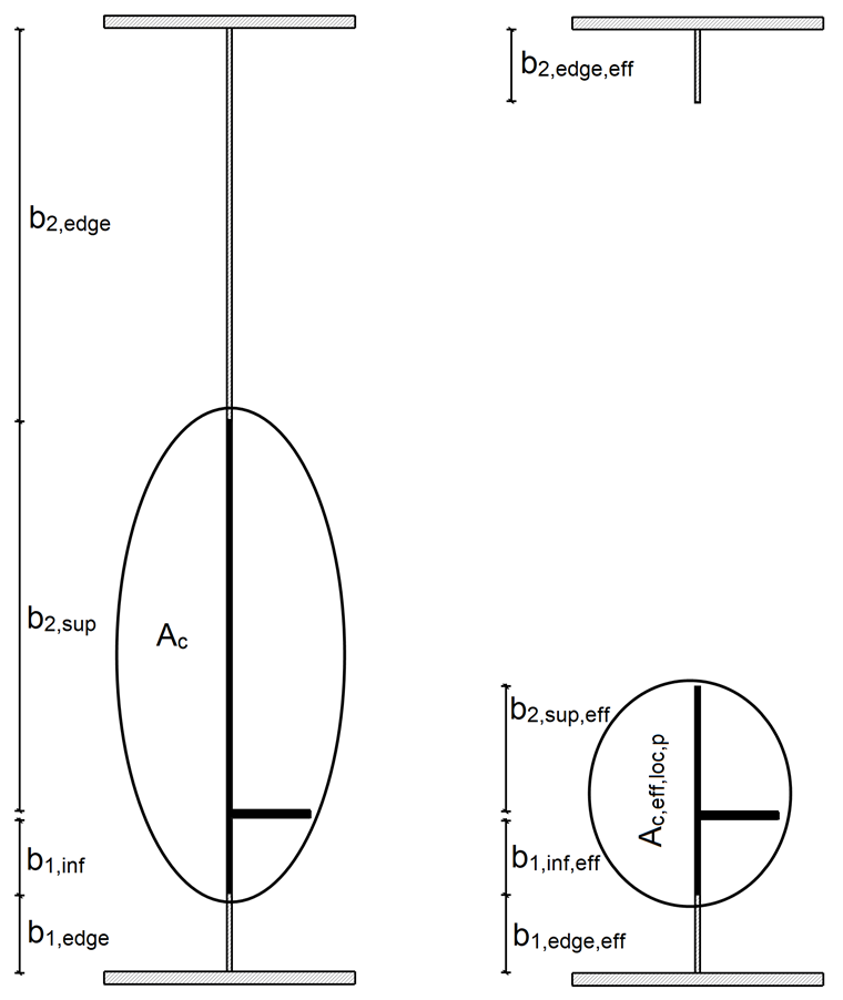
Isl,1 and Asl,1 describe the area moment of inertia of the gross cross-section and the gross cross-section area of the equivalent compression member according to [1]; A.2.1(2) for buckling perpendicular to the plate plane, and b1 and b2 describe the distances of the stiffeners to the longitudinal edges (b1 + b2 = b).
The stress distribution is uniform. Therefore, the elastic plate buckling stress σcr,p corresponds to the critical buckling stress σcr,sl.
The gross cross-section area Ac of the longitudinally stiffened plate panel is calculated as follows, without taking into account the edge plates supported by an adjacent plate component and the effective cross-section area Ac,eff,loc,p of the area described above:
The stiffness belongs to Cross-Section Class 3, so the effective cross-section area of the stiffness corresponds to the gross cross-section area of the stiffness.
The cross-section values are shown in Image 04.
The reduction factor βa,c,p is calculated according to [1], Section 4.5.2 as follows:
The global slenderness λp of the stiffened plate according to [1], Equation (4.7), results in:
According to [1], 4.4(2), the slenderness ratio λp is smaller than the limit value 0.673. Therefore, no reduction due to slab behavior is necessary; for example, ρp = 1.0.
Plate Buckling Behavior
The elastic critical buckling stress σcr,c is determined according to [1], Section 4.5.3(3). First of all, the buckling stress σcr,c,sl of the stiffener, which is positioned at the maximum loaded compression edge, is determined according to [1], Equation (4.9).
The stress distribution is uniform. Therefore, the elastic critical buckling stress σcr,c corresponds to the elastic buckling stress σcr,c,sl of the stiffener, which is positioned at the maximum loaded compression edge.
σcr,c = σcr,c,sl = 94.7 kN/cm²
The reduction factor βa,c,c is calculated according to [1], Section 4.5.3(4) as follows:
The slenderness ratio λcof the equivalent compression member according to [1], Equation (4.11), results in:
According to [1], Section 4.5.3(5), the radius of gyration i is calculated as follows:
The distance e is the greater of the two distances according to [1], Figure A.1; for example, either the distance e1 of the single stiffener, adjusted between the center of gravity and considered independently of the plate, without the effective width to the centroidal axis of the stiffened plate panel, or the distance e2 of the centroidal axis of the stiffened plate panel to the middle plane of the plate. The distances are shown in Image 05.

e = max (e1, e2) = max (10.39 cm, 2.86 cm) = 10.39 cm
The imperfection factor αe is determined, according to [1], Equation (4.12) with α = 0.49, for open stiffener cross-sections as follows:
The reduction factor χc is determined according to [3], 6.3.1.2:
Interaction Between Plate Buckling and Slab Behavior
The structural behavior of the entire panel is determined with the factor ξ, according to [1], Section 4.5.4(1):
The final reduction factor ρc is determined with the interaction equation according to [1], Equation (4.13):
Effective Cross-Section Values
The effective surface of the compression zone Ac,eff of the stiffened plate panel is calculated according to [1], Equation (4.5):
The effective cross-section area Aeff results in:

Design of Stiffened Panel
The centroidal axes of the gross cross-section and of the effective cross-section do not coincide, so additional acting bending moments due to the displacement of the centroidal axis of the effective cross-section related to the centroidal axis of the gross cross-section have to be considered here. These additional bending moments are calculated as follows:
The maximum stress results in:
The design is performed according to [1], Equation (4.15) as follows:
Torsional Buckling Design
According to [1], Section 9.2.1(8) the following criterion has to be fulfilled in general to avoid torsional buckling of stiffeners with open cross-sections:
Ip and ISt.Ven describe the polar moment of inertia and the St. Venant moment of inertia of the stiffness cross-section alone (without plate), calculated around the connection point to the plate.
If the warping stiffness is considered, the critical torsional buckling stress σcr has to be determined first. It is calculated according to [4], Equation (2.119) and Equation (2.120) as follows:
The stiffness has a warping constant of Iω = 0 cm6. The critical torsional buckling stress σcr is thus simplified to:
Ip and ISt.Ven describe the polar moment of inertia and the St. Venant moment of inertia of the stiffness cross-section alone (without plate), calculated around the connection point to the plate.
According to [1], Section 9.2.1(9), the criterion in 9.2.1(8) or the following criterion has to be generally considered, when taking into account the warping stiffness:
With a factor to ensure the elastic behavior according to Cross-Section Class 3 according to [5] of θ = 2 for stiffeners with low warping stiffness (for example, flat bar or bulb flat steel), the result is:
The torsional buckling design is thus fulfilled.
SHAPE-THIN
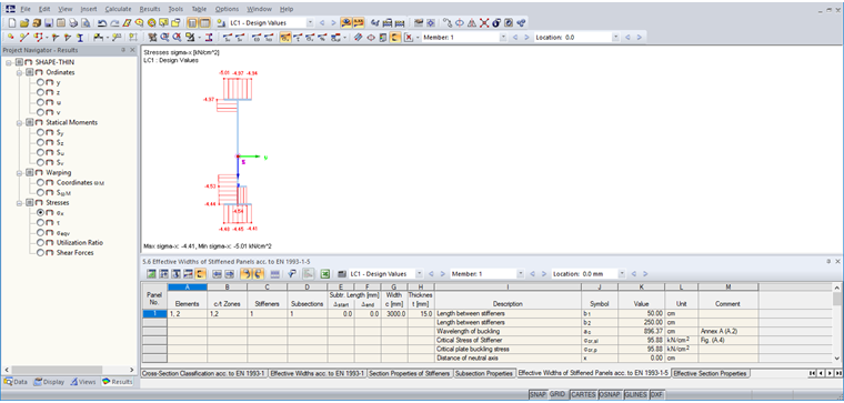
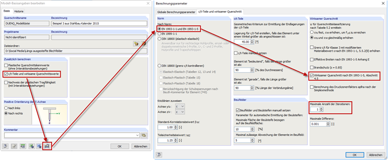
In SHAPE-THIN, the calculation of stiffened buckling panels can be performed according to [1], Section 4.5. The control panel "c/t parts and effective cross-section properties" has to be activated in the general data. Afterwards, it is necessary to select "EN 1993‑1‑1 and EN 1993‑1‑5" in the calculation parameters; the control panel titled "Effective cross-section according to EN 1993‑1‑5, Section 4.5" has to be selected as well. The determination of the effective widths should be carried out in an iterative process according to [1], Section 4.4(3). In this example, only one iteration has to be used for the calculation so that only one iteration will also appear in SHAPE-THIN (see Image 07).
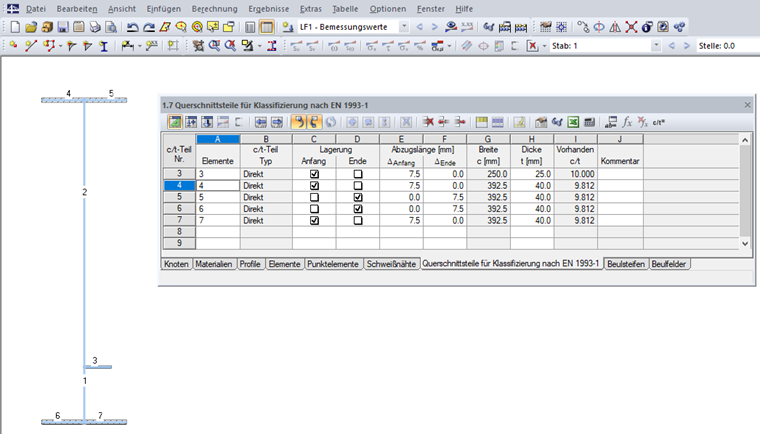
The elements of the cross-section have to be entered first. The c/t parts are generally generated automatically from the geometric conditions; however, they can be created as user-defined in Table "1.7 Cross-Section Parts for the Classification According to EN 1993‑1" (see Image 08) or the corresponding dialog box.
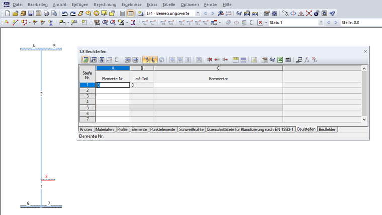
The stiffeners can then be defined in Table "1.8 Stiffeners" or in the corresponding dialog box (see Image 09).
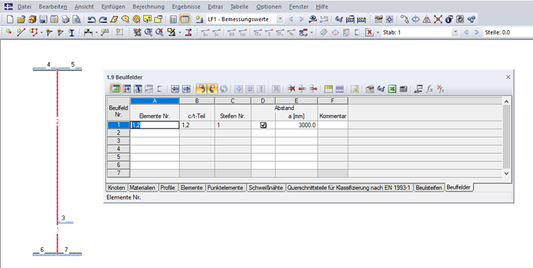
Moreover, the stiffened panel has to be specified in Table "1.9 Stiffened Panels" (see Image 10) or the corresponding dialog box. The elements of the stiffened panel have to be selected and the transverse stiffener distance a has to be entered. If no transverse stiffener distance is defined, the value a = 10,000 mm will be applied for the calculation. The stiffeners located in the stiffened panel are identified automatically. The stiffened panel has to be supported at its start and end, which means that a support is needed here.
The results of the effective cross-section can be viewed with the [Effective Widths" button.