Description
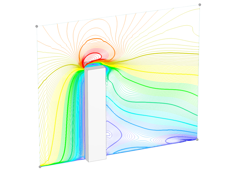
In the current validation example, we investigate the wind force coefficient (Cf) for cubic structures based on the European standard EN 1991-1-4 [1]. There are three-dimensional cases that we will explain in more detail in the next part.
One of the critical aspects of CFD simulation is selecting accurate and compatible configurations for input parameters such as turbulence models, wind velocity profiles, turbulence intensity, boundary layer conditions, and the order of discretization. However, the Eurocode (EN 1991-1-4) does not provide detailed guidance on these numerical settings. In the current example for a cubic structure, we recommend compatible settings regarding the Eurocode standard. As can be seen in EN 1991-1-4, there are different tables and diagrams for static calculation of wind load.
Analytical Solution
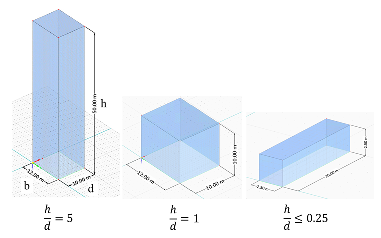
Cubic structures are classified into three-dimensional categories based on the height-to-depth ratio, as defined in Table 7.1 of EN 1991-1-4 and illustrated in Figure 1. The input parameters for each dimensional category are defined according to Table 1.
For the first case, a high-rise cube shape with a height-to-depth ratio of h/d=5 is considered. The corresponding input parameters are presented in the following table:
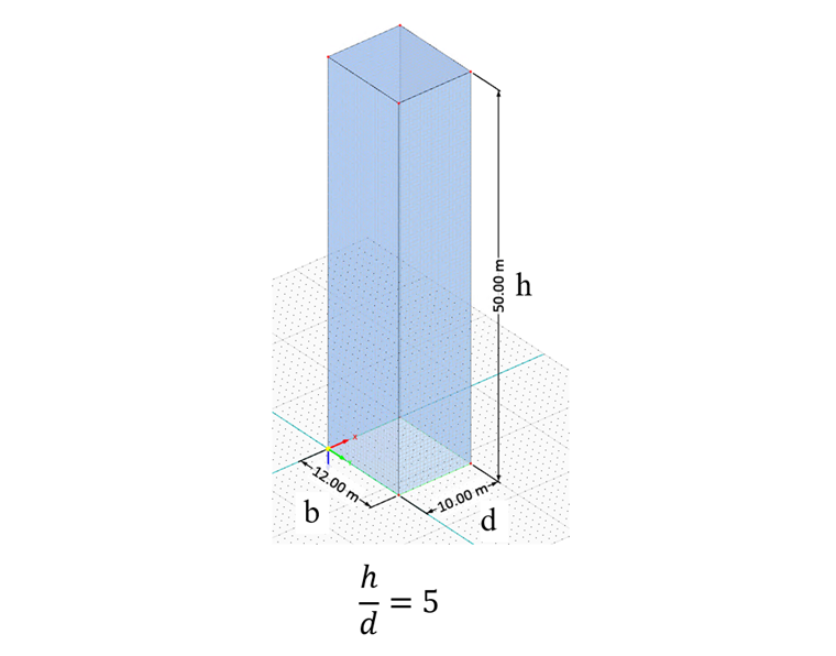
| Dimensional Ratio: h/d=5 | |||
| Wind Velocity | V | 30 | m/s |
| Height | h | 50 | m |
| Depth | d | 10 | m |
| Width | b | 12 | m |
| Solidity Ratio (Eq. 7.28, EN 1991-1-4) | φ | 1 | - |
| Effective Slenderness (Table 7.16, EN 1991-1-4) | λ | 5.83 | - |
| End-Effect Factor (Fig. 7.36, EN 1991-1-4) | ψλ | 0.68 | - |
| Reduction Factor (Fig. 7.24, EN 1991-1-4) | ψr | 1 | - |
| Force Coefficient Without Free-End Flow (Fig. 7.23, EN 1991-1-4) | Cf,0 | 2.30 | - |
| Force Coefficient (Eq. 7.9, EN 1991-1-4) | Cf | 1.564 | - |
| Air Density - RWIND | ρ | 1.25 | kg/m3 |
| Turbulence Model - RWIND | Steady RANS k-ω SST | - | - |
| Kinematic Viscosity (Equation 7.15, EN 1991-1-4) - RWIND | ν | 1.5*10-5 | m2/s |
| Scheme Order - RWIND | Second | - | - |
| Residual Target Value - RWIND | 10-5 | - | - |
| Residual Type - RWIND | Pressure | - | - |
| Minimum Number of Iterations - RWIND | 800 | - | - |
| Boundary Layer - RWIND | NL | 10 | - |
| Type of Wall Function - RWIND | Enhanced / Blended | - | - |
| Turbulence Intensity (Best Fit) - RWIND | I | 15% | - |
For the next case, a medium-rise cubic structure with a height-to-depth ratio of h/d=1 is considered. The corresponding input parameters are listed in the following table:
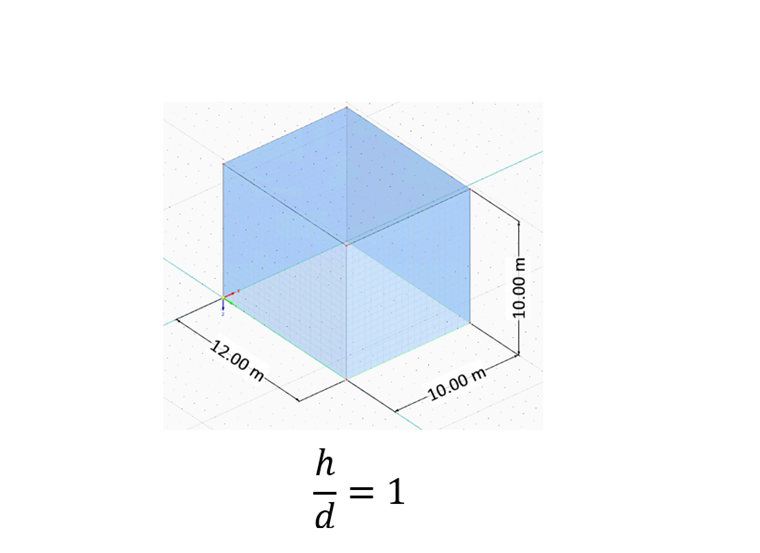
| Dimensional Ratio: h/d=1 | |||
| Wind Velocity | V | 30 | m/s |
| Height | h | 10 | m |
| Depth | d | 10 | m |
| Width | b | 12 | m |
| Solidity Ratio (Eq. 7.28, EN 1991-1-4) | φ | 1 | - |
| Effective Slenderness (Table 7.16, EN 1991-1-4) | λ | 1.66 | - |
| End-Effect Factor (Fig. 7.36 , EN 1991-1-4) | ψλ | 0.62 | - |
| Reduction Factor (Fig. 7.24, EN 1991-1-4) | ψr | 1 | - |
| Force Coefficient Without Free-End Flow (Fig. 7.23, EN 1991-1-4) | Cf,0 | 2.30 | - |
| Force Coefficient (Eq. 7.9, EN 1991-1-4) | Cf | 1.426 | - |
| Air Density - RWIND | ρ | 1.25 | kg/m3 |
| Turbulence Model - RWIND | Steady RANS k-ω SST | - | - |
| Kinematic Viscosity (Equation 7.15, EN 1991-1-4) - RWIND | ν | 1.5*10-5 | m2/s |
| Scheme Order - RWIND | Second | - | - |
| Residual Target Value - RWIND | 10-5 | - | - |
| Residual Type - RWIND | Pressure | - | - |
| Minimum Number of Iterations - RWIND | 800 | - | - |
| Boundary Layer - RWIND | NL | 10 | - |
| Type of Wall Function - RWIND | Enhanced / Blended | - | - |
| Turbulence Intensity (Best Fit) - RWIND | I | 7.5% | - |
For the final case, a low-rise cubic structure with a height-to-depth ratio of h/d=0.25 is considered. The corresponding input parameters are presented in the following table:
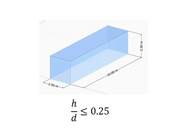
| Dimensional Ratio: h/d=0.25 | |||
| Wind Velocity | V | 30 | m/s |
| Height | h | 2.50 | m |
| Depth | d | 10 | m |
| Width | b | 2.50 | m |
| Solidity Ratio (Eq. 7.28, EN 1991-1-4) | φ | 1 | - |
| Effective Slenderness (Table 7.16, EN 1991-1-4) | λ | 2 | - |
| End-Effect Factor (Fig. 7.36, EN 1991-1-4) | ψλ | 0.63 | - |
| Reduction Factor (Fig. 7.24, EN 1991-1-4) | ψr | 1 | - |
| Force Coefficient Without Free-End Flow (Fig. 7.23, EN 1991-1-4) | Cf,0 | 1.20 | - |
| Force Coefficient (Eq. 7.9, EN 1991-1-4) | Cf | 0.756 | - |
| Air Density - RWIND | ρ | 1.25 | kg/m3 |
| Turbulence Model - RWIND | Steady RANS k-ω SST | - | - |
| Kinematic Viscosity (Equation 7.15, EN 1991-1-4) - RWIND | ν | 1.5*10-5 | m2/s |
| Scheme Order - RWIND | Second | - | - |
| Residual Target Value - RWIND | 10-5 | - | - |
| Residual Type - RWIND | Pressure | - | - |
| Minimum Number of Iterations - RWIND | 800 | - | - |
| Boundary Layer - RWIND | NL | 10 | - |
| Type of Wall Function - RWIND | Enhanced / Blended | - | - |
| Turbulence Intensity (Best Fit) - RWIND | I | 15% | - |
Results
The wind force coefficients (Cf) are evaluated for various height-to-depth ratios and turbulence intensities. For the first case, a high-rise cubic structurer with h/d=5, the resulting Cf value is presented in the following table:
| Turbulence Intensity (%) (h/d=5) | Fd (N) | ρ (kg/m3) | u (m/s) | A (m2) | Cf |
| 1.00 - RWIND | 498829 | 1.25 | 30 | 600 | 1.478 |
| 5.00 - RWIND | 518278 | 1.25 | 30 | 600 | 1.536 |
| 7.50 - RWIND | 521515 | 1.25 | 30 | 600 | 1.545 |
| 10.00 - RWIND | 520397 | 1.25 | 30 | 600 | 1.542 |
| 15.00 - RWIND | 525011 | 1.25 | 30 | 600 | 1.556 |
| 20.00 - RWIND | 533059 | 1.25 | 30 | 600 | 1.579 |
| 25.00 - RWIND | 543164 | 1.25 | 30 | 600 | 1.609 |
| Eurocode | - | - | - | - | 1.564 |
For the second case, a medium-rise cubic structure with h/d=1, the corresponding Cf value is presented in the following table:
| Turbulence Intensity (%) (h/d=1) | Fd (N) | ρ (kg/m3) | u (m/s) | A (m2) | Cf |
| 1.00 - RWIND | 97148 | 1.25 | 30 | 120 | 1.439 |
| 5.00 - RWIND | 95497 | 1.25 | 30 | 120 | 1.415 |
| 7.50 - RWIND | 96420 | 1.25 | 30 | 120 | 1.428 |
| 10.00 - RWIND | 96453 | 1.25 | 30 | 120 | 1.429 |
| 15.00 - RWIND | 96666 | 1.25 | 30 | 120 | 1.432 |
| 20.00 - RWIND | 91027 | 1.25 | 30 | 120 | 1.349 |
| 25.00 - RWIND | 89827 | 1.25 | 30 | 120 | 1.331 |
| Eurocode | - | - | - | - | 1.426 |
For the final case, a low-rise cubic structure with h/d=0.25, the corresponding Cf value is presented in the following table:
| Turbulence Intensity (%) (h/d=0.25) | Fd (N) | ρ (kg/m3) | u (m/s) | A (m2) | Cf |
| 1.00 - RWIND | 2711 | 1.25 | 30 | 6.25 | 0.771 |
| 5.00 - RWIND | 2692 | 1.25 | 30 | 6.25 | 0.766 |
| 7.50 - RWIND | 2671 | 1.25 | 30 | 6.25 | 0.760 |
| 10.00 - RWIND | 2667 | 1.25 | 30 | 6.25 | 0.759 |
| 15.00 - RWIND | 2650 | 1.25 | 30 | 6.25 | 0.754 |
| 20.00 - RWIND | 2662 | 1.25 | 30 | 6.25 | 0.757 |
| 25.00 - RWIND | 2630 | 1.25 | 30 | 6.25 | 0.748 |
| Eurocode | - | - | - | - | 0.756 |
Conclusion
The results demonstrate a strong agreement between the wind force coefficients obtained from RWIND simulations and those specified in the Eurocode (EN 1991-1-4). Based on the analysis, a recommended range of turbulence intensity is proposed for different height-to-depth (h/d) ratios. Specifically, turbulence intensities between 7.5% and 15% yield more accurate predictions of the wind force coefficient (Cf).
An addition key finding relates to the wind tunnel size used in the simulation. While the default wind tunnel dimensions were sufficient for the first two cases (h/d = 5 and h/d = 1), the final case (h/d = 0.25) required a modified wind tunnel size to achieve improved accuracy in the results.
The cube model with the recommended simulation settings is available to download here: