


The planning of the whole project was carried out according to the BIM method. An entire digital structure was created in the design phase, which was specified in detail during further planning.
The engineering office Grassl GmbH from Stuttgart was responsible for the structural design. They created the supporting structure in Revit and Tekla Structures and used the direct interfaces to RFEM to perform the structural analysis there. Cross-section modifications from structural analysis were transferred back to Revit and Tekla Structures and updated at the building model.
Factory Building
The factory building is composed of single-story production facilities of 28,000 m² (301,390 ft²) (Image 1, top), a technical and administration building with offices and staff rooms (Image 1, top left), and a high-bay warehouse (Image 1, top middle).
Whereas cast-in-place concrete was mainly used in the technical and administration building, reinforced concrete and precast prestressed concrete elements were used for the high-bay warehouse. Prefabricated columns, restrained at the bottom with a length of 30 m (99 ft) and a weight of up to 80 t (88 US t), as well as prestressed concrete girders with a length of 31.30 m (103 ft), were designed.
The one-story production hall has a planning grid of 24 m x 24 m (79 ft x 79 ft), in which restrained prefabricated reinforced concrete columns are arranged. The roof structure consists of steel trusses with parallel-chord main beams a = 24 m (79 ft) and secondary beams a = 6 m (20 ft).
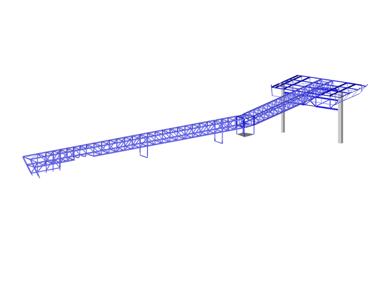
Pedestrian and Media Bridge
The media bridge, with an overall length of 106.20 m (349 ft), is designed as a thermally insulated steel truss structure with a width of 3.40 m (11 ft) and a height of about 2.45 m (8 ft). The spans vary, with a maximum span of 35.50 m (117 ft) in the subpanel. The pedestrian level is suspended as a steel structure from the underside of the media bridge via tension members.
Reinforced concrete columns form the bridge supports, which absorb vertical and lateral loads. A reinforced concrete shaft with stairs on the north side serves as a fixed point to absorb the axial forces of the bridge.
The advantages of model-based planning will continue to pay off even after completion of this BIM flagship project. This provides the client with a complete model with stored structural component information that supports them during operation, maintenance, conversions, and so on.
| Investor | SEW-Eurodrive GmbH & Co. KG www.sew-eurodrive.de |
| Architects | Studio Wolfhugel, Hoerdt, France, and Dill + Hauf Architekten |
| Structural Design | Ingenieurbüro Grassl GmbH www.grassl-ing.de |


