Home Downloads & Info References Customer Projects Big Dipper Coaster "Dynamite" in Theme Park Plohn, Germany
Big Dipper Coaster "Dynamite" in Theme Park Plohn, Germany
Customer Project
With Germany's first Big Dipper Coaster, you can experience spectacular roller coaster rides since May 2019. Since it was opened, the approximately 131 ft high and 547 yd long coaster has been one of the main attractions in the Plohn theme park in Vogtland, Saxony.
Client |
Freizeitpark Plohn GmbH www.freizeitpark-plohn.de/en |
Coaster Design and Manufacturer |
MACK Rides GmbH & Co KG www.mack-rides.com |
Structural Engineering, Workshop Planning, Geotechnical Engineering |
Weiß Beratende Ingenieure GmbH www.weiss-ingenieure.de |
- Length: ~ 360.9 ft
- Width: ~ 282.2 ft
- Height: ~ 131.2 ft
- Number of Nodes: 6858
- Number of Members: 10928
- Number of Cross-sections: 47
Model
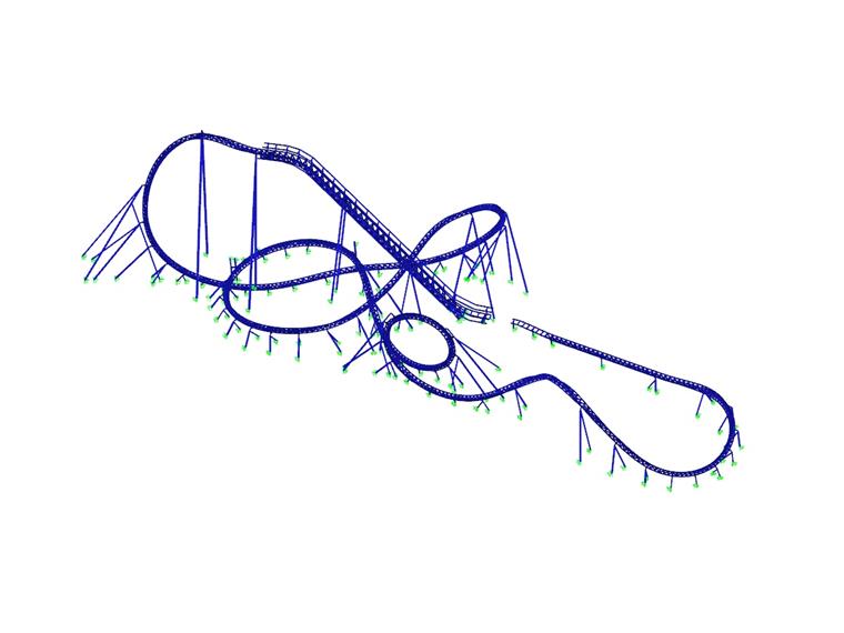
During the high-speed ride with speeds of up to 100 km/h including looping, helix and corkscrews, you can experience both accelerations of 4.4 g and the feeling of weightlessness. In addition, you go through a dark tunnel and later over it.
Big Dipper means that only one vehicle drives, four people each sit in two rows. The outer seats are quite far from the tracks, so you are floating next to the vehicle, so to speak.
Structural Analysis and Construction
Dlubal's customer Weiß Beratende Ingenieure performed the structural analysis of the roller coaster in RSTAB. For the fatigue calculation of the steel components, the internal forces were exported from RSTAB with the RS-COM interface and the fatigue designs were performed with a separate program. Weiß Beratende Ingenieure also calculated the station and the maintenance hall in RSTAB, as well as the tunnel including the decorational house (timber structure) in RFEM.
The approximately 547 yd long track of the Big Dipper forms a three-chord truss girder made of tubular steel sections. This truss girder is supported by a total of 76 columns. These are A-frames or fully restrained single columns. The roller coaster structure made of steel S 355 has a total weight of approx. 300 tons.
Project Location
Contact us
Do you have questions or need advice?
Contact our free e-mail, chat, or forum support or find various suggested solutions and useful tips on our FAQ page.
Recommended Events
Eurocode 3 | Steel structures according to DIN EN 1993-1-1
Online Training 18 March 2021 8:30 AM - 12:30 PM CET
Eurocode 3 | Steel structures according to DIN EN 1993-1-1
Online Training 6 May 2021 8:30 AM - 12:30 PM
Stability Design in Steel Construction with RFEM and RSTAB
Webinar 1 December 2020 2:00 PM - 2:45 PM CET
Designing Cold-Formed Steel Sections According to Eurocode 3
Webinar 30 April 2020 3:00 PM - 3:45 PM
Membrane Structures with Wind Loads From CFD Wind Simulation
Webinar 24 March 2020 3:00 PM - 4:15 PM CET
Videos
Models to Download
Knowledge Base Articles

New
Manual adjustment of the buckling curve according to EN 1993-1-1
The RF-/STEEL EC3 add-on module automatically transfers the buckling line to be used for the flexural buckling analysis for a cross-section from the cross-section properties. In particular for general cross -sections, but also for special cases, the assignment of the buckling line can be adjusted manually in the module input.
Screenshots
Product Features Articles

SHAPE-THIN | Cold-Formed Sections
SHAPE-THIN determines the effective cross-sections according to EN 1993-1-3 and EN 1993-1-5 for cold-formed sections. You can optionally check the geometric conditions for the applicability of the standard specified in EN 1993‑1‑3, Section 5.2.
The effects of local plate buckling are considered according to the method of reduced widths and the possible buckling of stiffeners (instability) is considered for stiffened sections according to EN 1993-1-3, Section 5.5.
As an option, you can perform an iterative calculation to optimize the effective cross-section.
You can display the effective cross-sections graphically.
Read more about designing cold-formed sections with SHAPE-THIN and RF-/STEEL Cold-Formed Sections in this technical article: Design of a Thin-Walled, Cold-Formed C-Section According to EN 1993-1-3.
Frequently Asked Questions (FAQ)
- I would like to calculate and design "temporary structures." What do I need for this?
- How is it possible to consider the real cross-section geometry of member elements in RWIND Simulation?
- Why do I get large differences for the design of a longitudinally stiffened buckling panel in comparison with the German and Austrian National Annex?
- How can I perform the stability analysis in RF‑/STEEL EC3 for a flat bar supported on edges, such as 100/5? Although the cross-section is rotated by 90° in RFEM/RSTAB, it is displayed as lying flat in RF‑/STEEL EC3.
- How can I create a curved or arched section?
- How are the signs for the release results of a line release and line hinges interpreted?
- How are hot-dip galvanized components considered for fire resistance in the RF‑/STEEL EC3 add-on module?
- How is the rotational stiffness of a buckling stiffener determined in PLATE‑BUCKLING?
- In RF‑/STEEL EC3, is the "Elastic design (also for Class 1 and Class 2 cross-sections)" option under "Details → Ultimate Limit State" considered for a stability analysis when activated?
- How can I get the member end forces to design the connections?
Customer Projects