Piccadilly Circus Spiral Staircase, London
Customer Project
-
04
Spiral Staircase Deformation in RFEM (© Matrix Consulting Engineers Ltd)
-
04
Piccadilly Circus Spiral Staircase, London (© Matrix Consulting Engineers Ltd)
-
04
Animation of Global Deformation of Spiral Staircase in RFEM | © Matrix Consulting Engineers Ltd | www.matrixce.co.uk
-
04
Our First Customer Project Designed with RFEM 6! | www.dlubal.com/customer-projects
-
05
Animation of Global Deformation of Spiral Staircase in RFEM | © Matrix Consulting Engineers Ltd | www.matrixce.co.uk
-
05
Spiral Staircase Deformation in RFEM (© Matrix Consulting Engineers Ltd)
-
05
Piccadilly Circus Spiral Staircase, London (© Matrix Consulting Engineers Ltd)
-
05
Our First Customer Project Designed with RFEM 6! | www.dlubal.com/customer-projects
This elegant steel spiral staircase is located in an office building in Sherwood Street, at Piccadilly Circus in central London.
Architect | Fletcher Priest Architects |
Owner |
D Wilson Architectural Metalworks Ltd www.dwilsonltd.com |
Structural Design |
Matrix Consulting Engineers Ltd www.matrixce.co.uk |
Model Data
Model
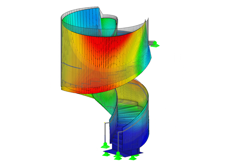
Based on the manufacturer's BIM model, the Matrix engineers created a 3D finite element analysis model to calculate the various stresses throughout the entire structure. In addition, it was necessary to ensure that the deflection of the stairs would be kept to a minimum so that no damage would occur to the terrazzo flooring.
The stair stringers (which also function as fall protection) as well as the steps are made of steel sheets t = 0.98 in. with a steel quality S275. The height of the stringers is approx. 4.59 ft. The Steel Design and Stress-Strain Analysis add-ons were used for the design in RFEM.
Project Location
1 Sherwood StreetLondon W1F 7BL
United Kingdom
Keywords
Write Comment...
Write Comment...
Contact Us
Do you have any further questions or need advice? Contact us via phone, email, chat or forum or search the FAQ page, available 24/7.
- The load distribution on my members looks different when using the Load Transfer surface vs. the Load Wizards. What is the reason?
- My beam has a continuous lateral support and therefore lateral torsional buckling (LTB) is not a concern. How do I define the effective length?
- I received an error message “Surface of incompatible type... (Surface in upper plane of building story must be of ‘Load transfer’ type)” when running the calculation. What is the reason?
- How can I efficiently define line hinges on several surfaces?
- How do I include the overstrength factor(s) Ωo in the ASCE 7 load combinations?
- How do I include the overstrength factor(s), Ωo in the ASCE 7 load combinations?
- My live load is less than or equal to 100 psf. How do I consider the reduced load factor in the ASCE 7 load combinations?
- How do I include the redundancy factor(s) ρ in the ASCE 7 load combinations?
- I do not see the seismic load cases in my generated ASCE 7 load combinations (COs). How do I add them?
- How do I create an imperfection based on a mode shape in RFEM 6?