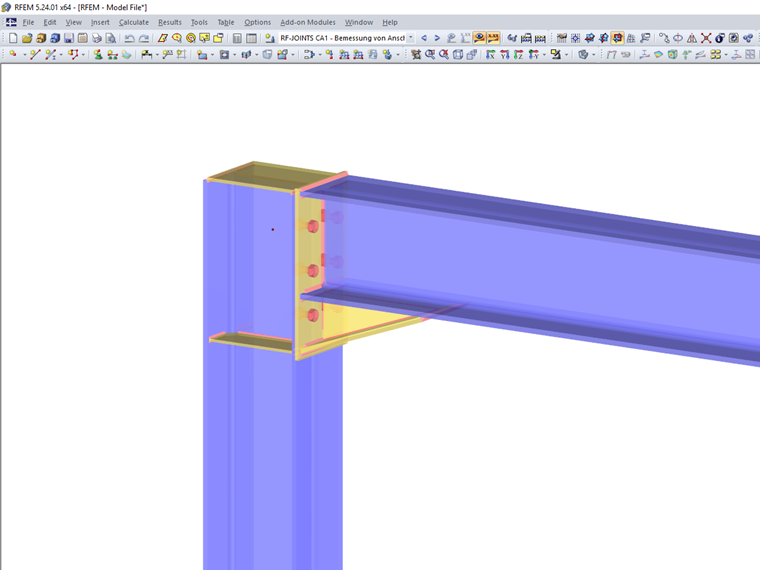
Contact us
Did you find your question?
If not, contact us via our free e-mail, chat, or forum support, or send us your question via the online form.
Recommended Events
Videos
Models to Download
Knowledge Base Articles

New
Automatically ignore curved c/t-parts when classifying cross-sections
The classification of cross-sections according to EN 1993-1-1 and EN 1993-1-5 can be carried out automatically in the RF-/STEEL EC3 add-on module. The maximum c/t ratios are specified in the standard for straight cross -section parts. There are no normative specifications for curved cross -section parts and therefore the cross -section classification cannot be performed for these cross -section parts.
Screenshots
Product Features Articles

SHAPE-THIN | Cold-Formed Sections
SHAPE-THIN determines the effective cross-sections according to EN 1993-1-3 and EN 1993-1-5 for cold-formed sections. You can optionally check the geometric conditions for the applicability of the standard specified in EN 1993‑1‑3, Section 5.2.
The effects of local plate buckling are considered according to the method of reduced widths and the possible buckling of stiffeners (instability) is considered for stiffened sections according to EN 1993-1-3, Section 5.5.
As an option, you can perform an iterative calculation to optimize the effective cross-section.
You can display the effective cross-sections graphically.
Read more about designing cold-formed sections with SHAPE-THIN and RF-/STEEL Cold-Formed Sections in this technical article: Design of a Thin-Walled, Cold-Formed C-Section According to EN 1993-1-3.
Frequently Asked Questions (FAQ)
- How can I get the member end forces to design the connections?
- Is it possible to calculate and design "temporary structures"? What do I need for this?
- How can I perform the design of the tension resistance of a smooth column in a smooth bucket column base, that is, the design against pulling out the column?
- How can I create a drilled beam in RFEM?
- In the RF‑/STEEL EC3 add-on module, I obtain an extremely high design ratio for a member in the case of "Biaxial bending, shear and axial force." Although the axial force is relatively high, the design ratio seems to be unrealistic. What is the reason?
- For which programs is the STEEL Warping Torsion add-on module available?
- I have just noticed that the STEEL EC3 add-on module also calculates with γM0 = 1.0 when designing a tension member, although it should actually be γM2 = 1.25. How can I perform the design correctly?
- Is it possible to design intermittent welds in the CRANEWAY add-on module?
- I design a cross-section created in the SHAPE‑THIN program by using the RF‑STEEL EC3 add-on module, but the program shows the error message "ER006 Invalid type of c/t-part for cross-section of type General." What can I do?
- For a buckling analysis, FE‑BUCKLING determines the governing shear stress of τ = 7.45 kN/cm², while RF‑/STEEL gives the result of the maximum shear stress of τ = 8.20 kN/cm². Where does this difference come from?