A result beam is used to summarize surface results in a virtual member. This allows you to determine the shear forces resulting from a surface, for example.
The position of the result beam in the model can be freely selected. It does not require any supports or a direct connection to the model, and no loads can act on it. However, it is necessary to assign a cross-section for design. This cross-section does not influence the stiffness of the overall system.
To create a result beam, select the line in the slab, for example, and double-click to open the “Edit Line” dialog box. Activate the “Beam” option and select the “Result Beam” member type in the dialog box that opens.
Insert image “Result Beam_Line”

Input
After selecting the “Result beam” member type, it is necessary to specify additional parameters. There are four options for specifying the integration area:
Integrate stresses and forces within the block with a square base: A square integration area is used, with its center of gravity located on the member axis.
Integrate stresses and forces within the cuboid: A rectangular integration area is used, whose center of gravity can vary.
Integrate stresses and forces within the cylinder: A circular integration area is used, whose center of gravity lies in the member axis.
Integrate stresses and forces of defined objects: Only those objects listed in the “Include Objects” list below and located within the possible area of effect (see the next section) are used for evaluation.
If the integration area overlaps objects that are not to be taken into account, these need to be selected in the “Excluded Objects” list.
Effective Area of Result Beam
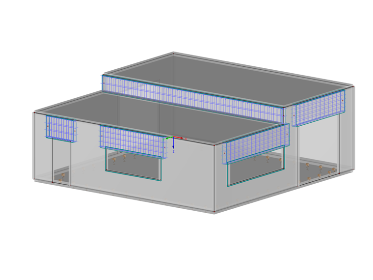
A result beam can only provide results for objects that are located within a rectangular axis between the member start and member end. All objects outside these boundaries are neglected.
For clarification: The areas marked in red in the image on the right are not used for the results. The turquoise surfaces were modeled manually as auxiliary surfaces and represent the boundaries of the result beam.

Cross-Section
The cross-section used is irrelevant for the internal forces of the member. Therefore, if the result beam is only to be used for determining internal forces, you can use any cross-section. However, if you want to perform subsequent design in add-on modules, such as RF-STEEL EC3 or RF-CONCRETE Members, the cross-section plays an important role and should be defined precisely.
Member Division of Results
Since the distribution of internal forces is not much reliable, it is necessary to set a higher number of member divisions for result diagrams in the global calculation parameters.

Position of Result Beam
For the internal forces N, Vy, and Vz, the parallel distance of the result beam to the centroid of the including objects does not matter. So if you want to only evaluate the axial and shear forces, you can model the result member on or above the structure to get a clear display.
However, it is crucial for the internal forces Mt, My, and Mz to place the result beam in the centroid of the including objects. In addition to including moments, the axial forces multiplied by the distance of each FE mesh point are added to the centroid of the result beam.