


Finite element analysis software such as RFEM allow you to determine internal forces and design stiffening structural elements. In this program, you can model a building including all structural components, openings, and other elements, and perform a calculation of the entire model.
Pre-dimensioning of the stiffening system can be performed using manual calculation according to the calculation method described in [1], or by using a program such as SHAPE‑THIN. This software provides engineers with a better understanding of the load transfer in a structure as well as the resistance contribution of the individual structural components.
Distribution of Horizontal Forces
The horizontal load distribution for bending or torsional loading on the stiffening components can be calculated according to the following formulas.
Forces due to Bending
where
Vy,i, Vz,i is the shear force in the y- or z‑direction, which affects the partial cross‑section i,
Vy, Vz is the shear force in the y- or z‑direction, which affects the gross cross‑section,
Iy,i, Iz,i, Iyz,i are the moments of inertia of the partial cross‑section i relating to the parallel axes Y and Z by the partial cross‑section centroid Si,
Iy, Iz are the total second moments of area relating to the overall centroid S.
Forces due to Torsion
where
Vy,i, Vz,i is the shear force in the y- or z‑direction, which affects the partial cross‑section i,
Mxs is the secondary torsional moment, which affects the gross cross‑section,
Iy,i, Iz,i, Iyz,i are the moments of inertia of the partial cross‑section i relating to the parallel axes Y and Z by the partial cross‑section centroid Si,
Iω,i is the warping constant related to the shear center Mi of the partial cross-section,
yM,i, zM,i is the coordinate of the shear center of the partial cross‑section Mi,
yM, zM is the coordinate of the overall shear center M.
Example
The distribution of horizontal loads in the stiffening elements is explained on the system displayed in Image 01.
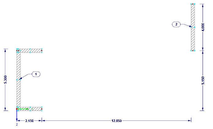
Wall thickness t = 30 cm
Section Properties
Partial Cross-Section 1
Partial Cross-Section 2
Gross Cross-Section
Iy = 10.668 + 1.600 = 12.268 m4
Iz = 1.084 + 0.009 = 1.093 m4
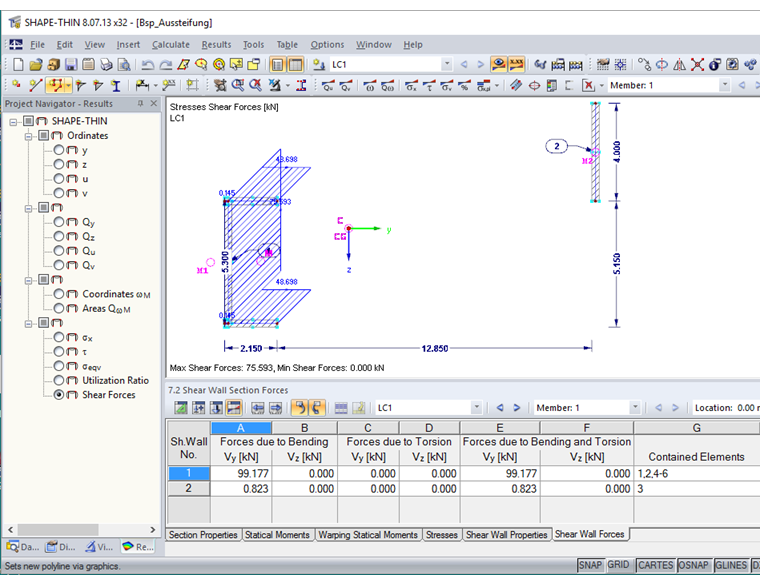
The cross-section properties determined in SHAPE-THIN 8 are displayed in Image 02.

Shear Forces of Partial Cross-Section
The shear forces of the partial cross-section determined in SHAPE-THIN 8 are displayed in Image 03.
References
[1] Beck, H., & Schäfer, H. (1969). Die Berechnung von Hochhäusern durch Zusammenfassung aller aussteifenden Bauteile zu einem Balken. Der Bauingenieur, Heft 3.