


Design According to EC2-1-1
It is necessary to verify that the effective shear force vEd does not exceed the absorbable shear forces vRd,max and vRd,s:
The longitudinal shear force vEd is determined by the relation
. ΔFd corresponds to the longitudinal force difference, which occurs in a one-sided chord section on the length Δx. To determine this longitudinal force difference, the compression chord force Fcd,a and the tensile chord force Fsd,a are required. The maximum value that may be assumed for Δx is half the distance between the section where the moment is 0 and the section where the moment is maximum. In the case of applying point loads, the length Δx should not exceed the distance between point loads.![Formula Symbols for Connection Between Chords and Web (Source: [1])](/en/webimage/009346/2418256/01-en-3-png.png?mw=760&hash=459cd80d886273f46fdc005fa46bb8c50f8e61d1)
The reinforcement for absorbing the tensile forces in the plate that is transverse to the web is determined as follows:
Furthermore, it must be verified that the load-bearing capacity of the compressive strut (A in Image 01) is not exceeded in the flange. For this, Equation
applies.If there is transverse bending of the plate and longitudinal shear between the web and flange at the same time, you should use the larger steel cross-section, which results from the two designs for the upper position in the plate. This also means that the upper transverse bending reinforcement can be completely compensated for the upper position of the shear reinforcement.
Considering Shear Between Web and Flange in RF-CONCRETE Members
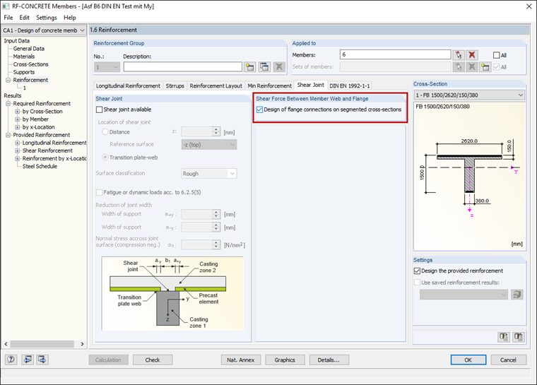
Shear joints can be considered in RF‑CONCRETE Members, in Window 1.6 Reinforcement under the "Shear Joint" tab.
Results of Shear Joint Design
Windows 2.1 to 2.4 show the resulting required reinforcement. These results can be displayed by cross-section, by set of member, by member, or by x-location.
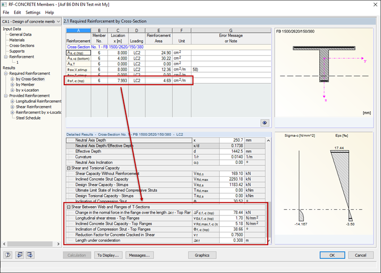
The result of the required reinforcement for the shear joint is displayed together with the result of the shear reinforcement by section length asf. In the "Detailed Results" table, you can see some intermediate values of the shear design between flange and web. These intermediate values are listed under the results of "Shear Between Web and Flanges of T-Sections".