


Defining Effective Length in RFEM 6
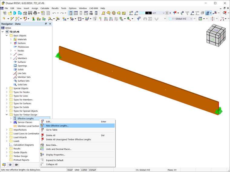
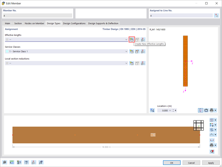
If you have already worked with RFEM 6, you probably know that the effective length is not a local setting of just one member. This means that each effective length defined in the program can be assigned to several members or member sets at the same time. The "Effective Length" dialog box can therefore be opened both via the Data tab of the navigator (Image 1) and via the Design Types tab of the member window (Image 2).
Intermediate Nodal Supports Without Eccentricity
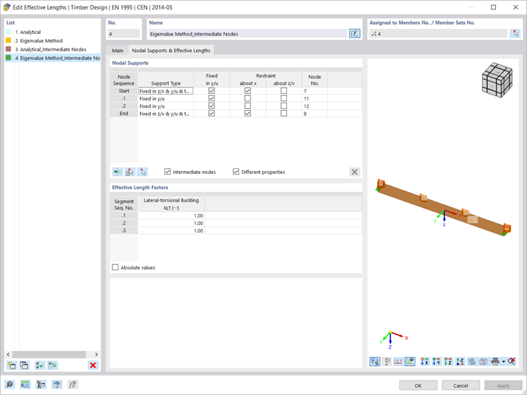
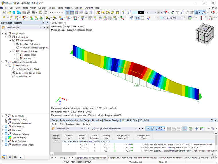
Let's first look at the results when the effective length for lateral-torsional buckling is determined taking into account the nodal supports defined in Image 3 (that is, no eccentricity being introduced). You can see that in addition to the start and end nodes, two intermediate nodes with different properties are inserted as shown in the image. This is represented graphically in the view on the right side of the dialog box. The effective length defined in this way is then assigned to the member and the results of the timber design are shown in Image 4.
As already mentioned in the introduction, there is an RFEM 6-specific function for determining the critical bending moment by which you can assign an eccentricity to the nodal supports. The eccentricity refers to the lateral support in y/u and can have a stabilizing or destabilizing effect on lateral-torsional buckling, depending on the position of the compression flange. This is shown in the example by assigning the eccentricity to the two intermediate supports.
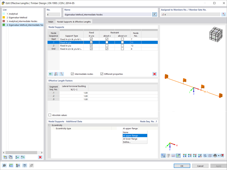
To assign an eccentricity to the supports, open the "Nodal Supports and Effective Lengths" dialog tab and select the intermediate nodes in the "Nodal Supports" section (Image 5). You will notice that a new section is now available at the bottom of the dialog box where you can define additional data for the nodal support. So, you can define a support on a top or bottom flange. You also have the option to manually define the eccentricity. Please note that the entry refers to the row selected above in the "Nodal Supports" table. In this example, the two intermediate nodal supports are defined on the top flange, which you can also see in the view on the right side of the dialog box.
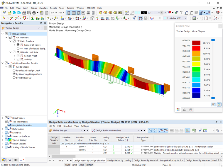
When defining the intermediate nodal supports at the upper flange, the results are as shown in Image 6.
Summary
The “Nodal Supports – Additional Data” dialog section is displayed in the “Nodal Supports & Effective Lengths” tab if a spring has been defined as a support, or if there is a lateral support in y/u without rigid restraint about x. The entry refers to the row selected in the "Nodal Supports" table. With this RFEM 6-specific function, you can define an eccentricity that can have a stabilizing or destabilizing effect for the lateral-torsional buckling, depending on the position of the compression flange. A list is available for you to define the support on an upper or lower flange. There is also the option to define the support manually by setting the ez eccentricity value. This is then taken into account accordingly in the results of the stability analysis.