As part of the linear eigenvalue calculation using the Structure Stability add-on, "Modal Relevance Factors" (MRF) are now also shown for all mode shapes and individual members in addition to the critical loads and the equivalent effective lengths determined from these loads. The MRF qualitatively describes the relevance of a member for a calculated mode shape. The calculation is based on the elastic deformation energy, which results for each individual member (k) in the mode shape (i). Since the mode shapes can be scaled as required, no absolute deformation energies are considered. Instead, the energies of all single members are put in relation to one another:
where
- ui is the mode shape for eigenvalue i,
- Kek is the element stiffness matrix for member k.
An MRF of 100% means that a single member has maximum relevance for the considered mode shape. Members that have no significant deformation energy in comparison are, however, of no interest for the mode shape under consideration.
As part of the stability analysis evaluation by mode shape, the MRF can be used to quickly and systematically differentiate between local and global mode shapes. If several individual members have an MRF significant for a mode shape (for example, greater than 20%), this indicates an instability of the entire structure or a part of it. However, if the sum of all MRFs is about 100% for a mode shape, a local stability phenomenon (for example, buckling of a single member) is to be expected.
In addition, the MRF can be used to determine governing critical loads and equivalent effective lengths of particular members (for example, for the stability design). Here, a member-by-member evaluation of the analysis results is recommended. Mode shapes for which the member has small MRF values (for example, less than 20%) can be neglected without problems when finding the member's critical effective length.
Example
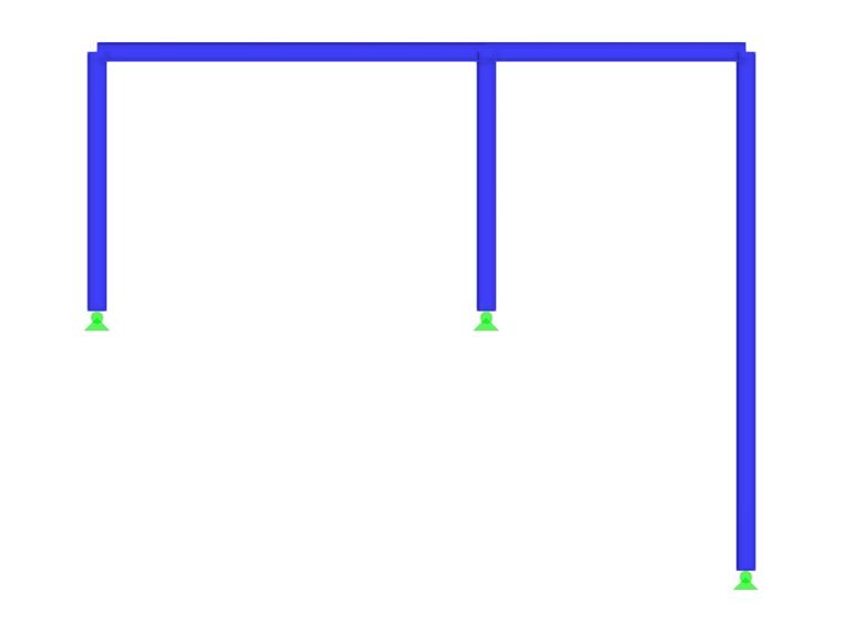
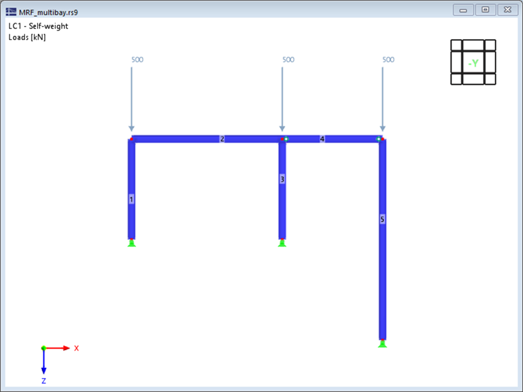
In the following, the significance of the MRF is demonstrated using a simple example. A two-hinged frame with an individual pin-ended column (right column) is considered in the plane as shown in Image 1. A linear stability analysis is carried out for the stress shown, applying the default settings.
Evaluation of Mode Shapes by Engineering Expertise
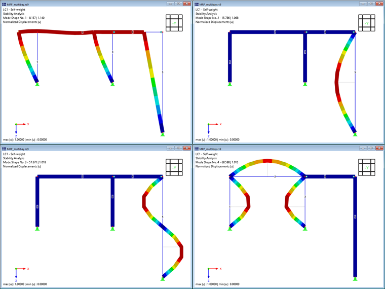
The first four mode shapes of the structure are shown in Image 2; they can be characterized as follows:
- The first mode shape is characterized by the frame's lateral instability. The pin-ended members 4 and 5 show large displacements, but only follow the lateral movement of the frame, so that no significant deformation energy arises in these members.
- Mode shapes 2 and 3, however, can be identified as isolated buckling shapes of the pin-ended column (member 5). The frame ensures a lateral support of the column head, so that the column's stability can also be idealized as Euler buckling mode II (first and second mode shapes about major axis).
- The fourth mode shape again shows buckling of the frame shafts. However, as in the first mode shape, the rigidly connected horizontal beam contributes to an increase of the critical load.
Objective Analysis Using MRF
In addition to the "manual" analysis and evaluation of mode shapes, the user now has an objective auxiliary factor at his or her disposal. Image 3 shows the "Effective Lengths and Critical Loads by Mode Shape" result table for the example system. The modal relevance factors calculated by member confirm that the mode shapes 1 and 4 are dominated by the rigid frame (members 1-3), while the pin-ended members 4 and 5 have no relevance (MRF = 0%). In contrast, only member 5 (MRF = 100%) participates in mode shapes 2 and 3; a quick look at the result table reveals that these mode shapes must therefore be a local stability failure.
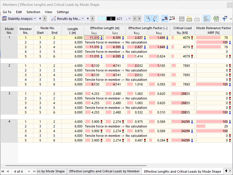
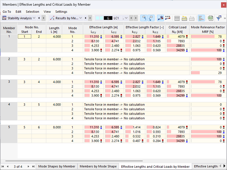
The member-by-member representation of the modal relevance factors (see Image 4) is suitable for determining the governing effective lengths and critical loads of the individual members. The selected example represents a planar structural system; a deviation from the frame plane (about the minor member axis) is not possible due to the selected basic settings. Thus, only the strong (y-)axis is important here for the analysis of the governing effective lengths and critical loads.
The results shown in Image 4 imply that the first mode shape should be applied in a stability analysis of the frame posts (Members 1 and 3). Here, the critical load is minimal for the mode shapes in which the frame posts participate (1 and 4). For the buckling analysis about the major axis using the equivalent member method, a buckling length coefficient of 2.827 should be selected. For the pin-ended column (Member 5), however, mode shape 2 with an effective length coefficient of 1.016 would be governing. The lowest critical load is also calculated here for mode shape 1, but the pin-ended column does not participate in this mode shape (MRF = 0 %).
In order to make the tabular MRF analysis clearer, we advise filtering out all MRFs up to a certain limit value (for example, less than 20%) using the "Result Table Manager".