70 Results
View Results:
Sort by:
![Spectral Acceleration Sa [m/s²] Versus Natural Frequency f [Hz] of Narrow-Band Response Spectrum According to EN 1998-1 [1]](/en/webimage/009251/2417757/01-en-png.png?mw=640&hash=c76563b459152b19c98197ea6ba342be89d9a5bc)
In a multi-modal response spectrum analysis, it is important to determine a sufficient number of eigenvalues of the structure and to consider their dynamic responses. Regulations such as EN 1998‑1 [1] and other international standards require the activation of 90% of the structural mass. This means: to determine so many eigenvalues that the sum of the effective modal mass factors is greater than 0.9.
Structures react differently to wind action depending on stiffness, mass, and damping. A basic distinction is made between buildings that are prone to vibration and those that are not.
![Vibration Analysis (Source: [3])](/en/webimage/009798/467822/01-de-png.png?mw=640&hash=52805a227240ecddbd69b1d113348bf2749c3f9e)
The vibration design of cross‑laminated timber plates often governs for wide-span ceilings. The advantage of timber as a lighter material compared to concrete is turned into a disadvantage here, since a high mass is advantageous for a low natural frequency.
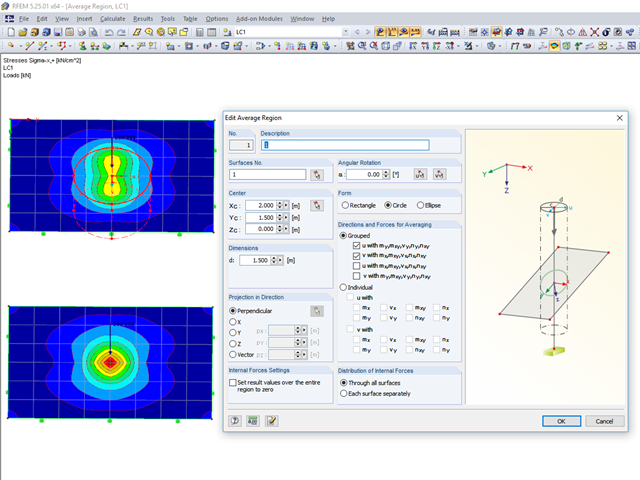
RFEM 5 provides the option to define a smoothing area in the "Results" → "New Average Region" menu. You can choose a rectangular, circular, or elliptical shape. With this tool you can, for example, "smooth" singularities due to nodal loads in a desired averaged region.
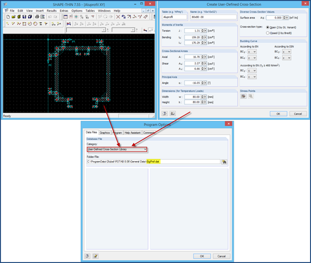
There are two ways of adding cross‑sections that are not included in the extensive cross‑section library: 1. You can create the cross‑section in the cross‑section programs SHAPE‑THIN or SHAPE‑MASSIVE and import it to RFEM/RSTAB. 2. If the cross‑section properties are provided by the manufacturer, you can add it to the RFEM/RSTAB cross‑section library using the option "New User‑Defined Cross‑Section".
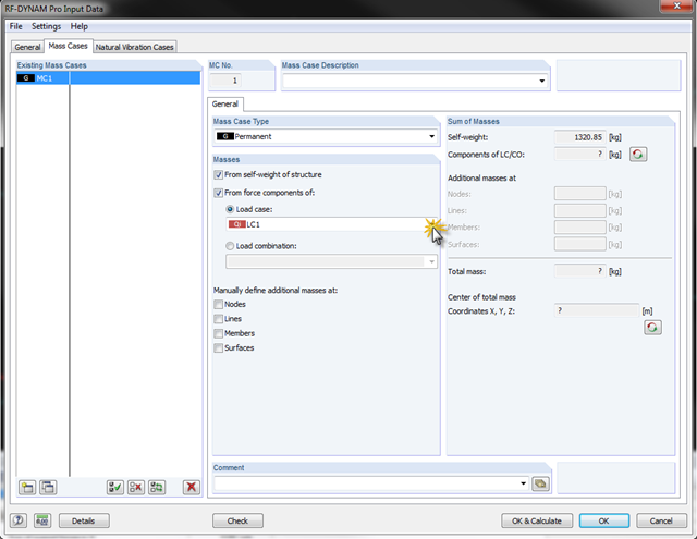
In RF-/DYNAM Pro - Natural Vibrations, it is possible to transfer complete load cases/load combinations as masses. To do this, you can simply save the load case or the load combination to be considered as a mass case in the add‑on module.

The stand-alone program RSECTION is at your disposal for determining section properties and performing stress analysis for thin-walled and massive cross-sections. The program can be connected to both RFEM and RSTAB so that sections from RSECTION are also available in the RFEM and RSTAB library. Likewise, internal forces from RFEM and RSTAB can be imported into RSECTION.

The "Generate Snow Loads" function provides the option to take snow overhang into consideration. Thus, the load of the snow overhang is applied automatically to the eaves using a distributed load or several nodal loads.

RF-PUNCH Pro performs punching shear design on concentrated load application locations (column connection, nodal support, and nodal load) as well as on wall ends and wall corners.

The SHAPE‑THIN and SHAPE‑MASSIVE cross-section programs are suitable for determining the cross-section properties of common thin-walled or thick-walled sections. These cross-section properties are also available for further analyses in RSTAB and RFEM.
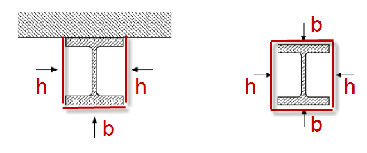
For unprotected I‑sections, the standard provides the correction factor ksh according to Equation 4.26a in Section 4.2.5.1 (2) to consider the shadowing effect. The term [Am/V]b is used there. This section factor includes Am, which represents the box enclosing the cross‑section (Index b = boxed). In the case of a three-sided fire exposure (a girder with a massive ceiling), the flange surface not exposed to fire is not taken into account when determining [Am/V]b.

You can use the stand-alone program RSECTION to determine the section properties for any thin-walled and massive cross-sections, as well as to perform a stress analysis. The previous Knowledge Base article titled "Graphical/Tabular Creation of User-defined Cross-sections in RSECTION 1" discussed the basis of defining cross-sections in the program. This article, on the other hand, is a summary of how to determine the section properties and perform a stress analysis.

Nodal supports are usually defined with regard to the global axis system. However, it is sometimes necessary to rotate the nodal support. For example, for a floor slab with a pile foundation. For geological reasons, the piles do not rest in the ground vertically, but in an inclined position. Each end point of the piles has a nodal support that can only absorb forces along the pile foundation direction. Therefore, rotating the nodal support is required. Various options for this are described in previous posts.
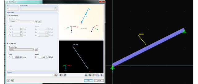
In RFEM and RSTAB, you can now rotate nodal loads or apply them on member axes. Thus, inclined members can also be loaded with nodal loads perpendicularly or along the member axis.

In RFEM 6, the results for the FE mesh nodes are determined using the finite element method. For the distribution of internal forces, deformations, and stresses to be continuous, these nodal values are smoothed through an interpolation process. This article will introduce and compare the different types of smoothing that you can use for this purpose.
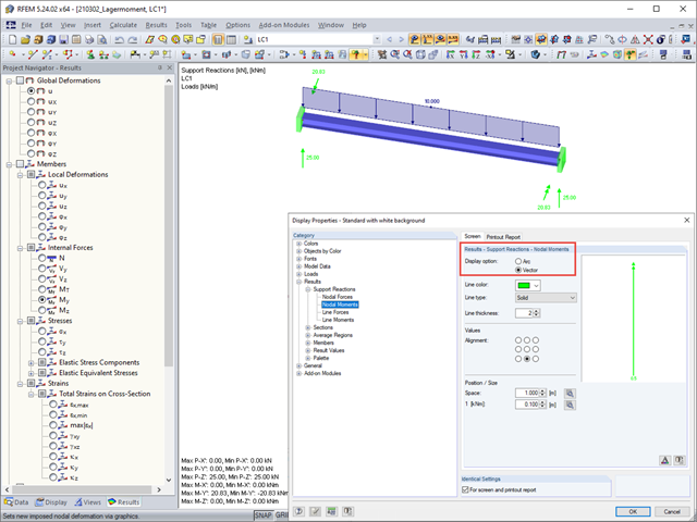
In the display properties, you can select Results → Support Reactions → Nodal Moments to specify whether a support moment should be displayed as an arc or a vector.

The optimal scenario in which punching shear design according to ACI 318-19 [1] or CSA A23.3:19 [2] should be utilized is when a slab is experiencing a high concentration of loading or reaction forces occurring at one single node. In RFEM 6, the node in which punching shear is an issue is referred to as a punching shear node. The causes of these high concentration of forces can be introduced by a column, concentrated force, or nodal support. Connecting walls can also cause these concentrated loads at wall ends, corners, and ends of line loads and supports.

The punching shear design, in line with EN 1992-1-1, should be performed for slabs with a concentrated load or reaction. The node where the design of punching shear resistance is performed (that is, where there is a punching problem) is called a node of punching shear. The concentrated load at these nodes can be introduced by columns, concentrated force, or nodal supports. The end of the linear load introduction on slabs is also regarded as a concentrated load and therefore, the shear resistance at wall ends, wall corners, and ends or corners of line loads and line supports should be controlled as well.

For structural components consisting of slabs, it is necessary to perform shear design on the locations with concentrated load introduction, applying the punching shear design rules according to Sect. 6.4 of EN 1992‑1‑1 [1]. The concentrated load introduction is present on the individual locations; for example, by columns, concentrated load, or nodal supports. In addition, the end of linear load introduction on slabs is also regarded as concentrated load introduction. For example, this includes wall ends, wall corners, and ends or corners of line loads and line supports. You can perform the punching shear design for floor slabs or foundations, considering the existing available plate topology about the designed node of punching shear. The punching shear design according to EN 1992‑1‑1 checks that the acting shear force vEd does not exceed the resistance vRd.

When evaluating line support forces, implausible diagrams sometimes arise at first glance. In particular, for variable loads at locations that also have a nodal support, at division points and edge locations of supported lines, the results sometimes show unexpected support reactions. Using the function of the linear smooth distribution in Project Navigator – Display does not always lead to the expected result diagram.