- Design of member ends, members, nodal supports, nodes, and surfaces
- Consideration of specified design areas
- Check of cross-section dimensions
- Design according to EN 1995-1-1 (European Timber Standard) with the respective National Annexes + DIN 1052 + DSTV DIN EN 1993-1-8 + ANSI / AWC - NDS 2015 (US Standard)
- Design of various materials, such as steel, concrete, and others
- No necessary linking to specific standards
- Extensible library including timber fasteners (SIHGA, Sherpa, WÜRTH, Simpson StrongTie, KNAPP, PITZL) and steel fasteners (standardized connections in steel building design according to EC 3, M-connect, PFEIFER, TG-Technik)
- Ultimate load capacities of timber beams by the companies STEICO and Metsä Wood available in the library
- Connection to MS Excel
- Optimization of connecting elements (the most utilized element is calculated)
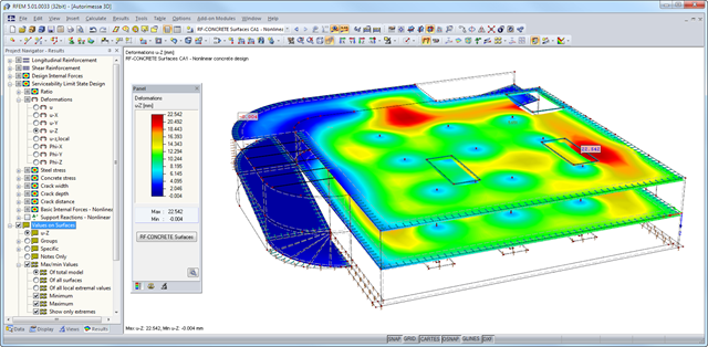
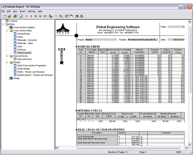
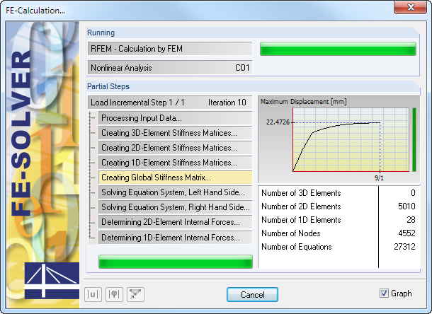
After the calculation, the module shows clearly arranged tables listing the results of the nonlinear calculation. All intermediate values are included in a comprehensible manner. Graphical representation of design ratios, deformations, concrete and reinforcing steel stresses, crack widths, crack depths, and crack spacing in RFEM facilitates a quick overview of critical or cracked areas.
Error messages or remarks concerning the calculation help you find design problems. Since the design results are displayed by surface or by point including all intermediate results, you can retrace all details of the calculation.
Due to the optional export of input or result tables to MS Excel, the data remain available for further use in other programs. The complete integration of results in the RFEM printout report guarantees verifiable structural design.
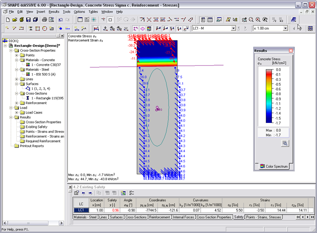
- Stresses σ and strains ε of concrete and reinforcement without considering concrete tensile strength (state II)
- Ultimate limit state design (existing safety) or design of defined internal forces
- Location of the neutral axis α0, y0,N, z0,N
- Curvatures ky, kz
- strain in the zero point ε0 and governing strains at the compression edge ε1 and at the tension edge ε2
- Governing steel strain ε2s
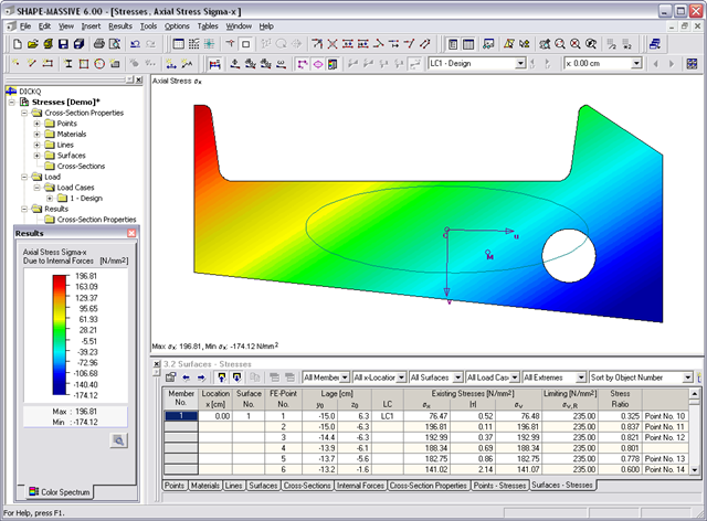
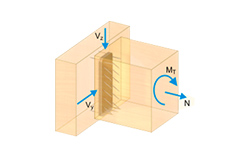
- Normal stresses σx due to axial force and bending
- Shear stresses τ due to shear force and torsion
- Equivalent stresses σv compared to limit stress
- Stress ratios related to equivalent stresses
- Normal stress σx due to unit axial force N
- Shear stress τ due to unit shear forces Vy, Vz, Vu, Vv
- Normal stress σx due to unit momentsMy, Mz, Mu, Mv
It is possible to freely model a cross-section using surfaces limited by polygonal lines, including openings and point areas (reinforcements). Alternatively, you can use the DXF interface to import the geometry. An extensive material library facilitates the modeling of composite cross-sections.
Definition of limit diameters and priorities allows for a curtailment of reinforcements. In addition, you can consider the respective concrete covers and prestresses.
- Iterative nonlinear calculation of deformations for beam and plate structures consisting of reinforced concrete by determining the respective element stiffness subjected to the defined loads
- Deformation analyses of cracked reinforced concrete surfaces (state II)
- General nonlinear stability analysis of compression members made of reinforced concrete; for example, according to EN 1992-1-1, 5.8.6
- Tension stiffening of concrete applied between cracks
- Numerous National Annexes available for the design according to Eurocode 2 (EN 1992-1-1:2004 + A1:2014, see EC2 for RFEM)
- Optional consideration of long-term influences such as creep or shrinkage
- Nonlinear calculation of stresses in reinforcing steel and concrete
- Nonlinear calculation of crack widths
- Flexibility due to detailed setting options for basis and extent of calculations
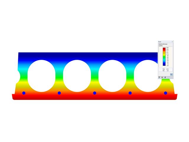
- Graphical representation of results integrated in RFEM; for example, deformation or sag of a flat slab made of reinforced concrete
- Numerical results clearly arranged in tables and graphical display of the results in the model
- Complete integration of results in the RFEM printout report
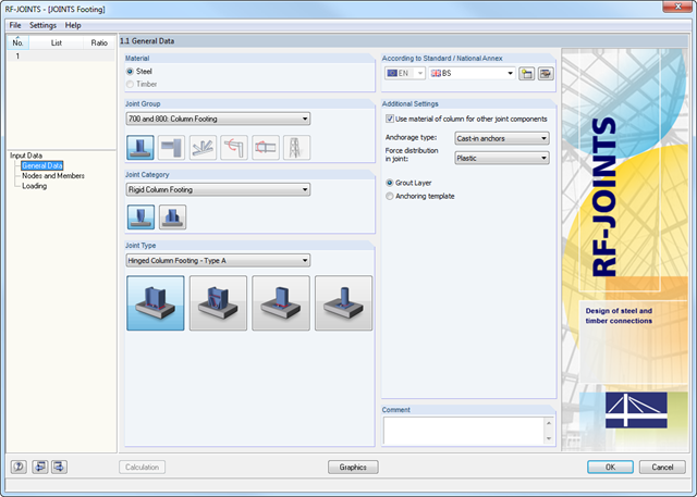
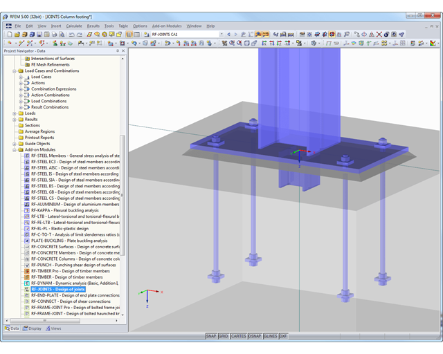
The Hinged Column Footing category provides four different base plate connections:
- Simple column base
- Tapered column base
- Column base for rectangular hollow sections
- Column base for circular hollow sections
The Restraint Column Footing category provides five different joint layouts of I-sections:
- Base plate without stiffening
- Base plate with stiffeners in center of flanges
- Base plate with stiffeners on both sides of column
- Base plate with channel sections
- Pocket foundation
All connection types include a base plate welded around a steel column. Connections with anchors are set in concrete within the foundation. You can select anchor types M12 – M42 with steel grades of 4.6 – 10.9. The top and bottom sides of the anchors can be provided with round or angled sheets for better load distribution or anchorage. In addition, you can use rectangular or circular anchor heads with threads applied at the member ends.
The material and thickness of the grout layer, as well as the dimensions and material of the footing, can be set freely. Furthermore, you can define edge reinforcement of the footing. For a better transfer of shear forces, it is possible to arrange a shear key (cleat) on the bottom side of the base plate.
Shear forces are transferred by a cleat, anchors, or friction. You can combine the individual components.
After the calculation, RF-/JOINTS Steel - Column Base displays the following design results:
- Net section design
- Bearing resistance design
- Shear
- Block shear resistance
- Sliding
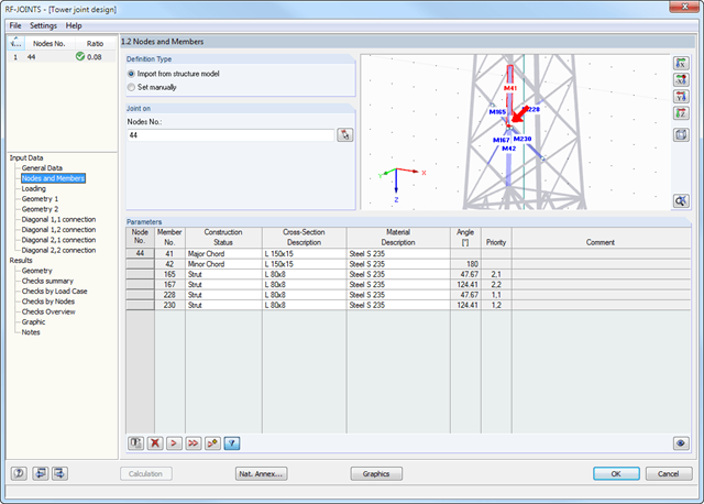
After you have selected the joint type, the connection category, and the design standard in the first input window, you can define the node to be imported from RFEM/RSTAB and to be used for the design of the joint in Window 1.2. Optionally, you can define the connection geometry manually.
In the other input windows, you can then define the parameters of the connection, such as The loading is imported from RFEM/RSTAB or, in the case of manual joint definition, loads are entered.
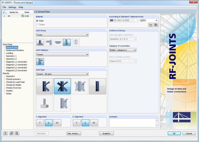
- Wide range of joint types, for example:
- Bolted connection of diagonals without gusset plate 2D
- Bolted connection of diagonals without gusset plate 3D
- Bolted column joint
- T-, K-, and KT-joints considered for connections of diagonals
- Various categories of connections:
- A - shear/hole bearing connection
- B - slip-resistant connection at serviceability limit state
- C - slip-resistant connection at ultimate limit state
- Bolt strength classes of 4.6 - 10.9
- Bolt diameters M12 - M42
- Modifiable bolt spacing
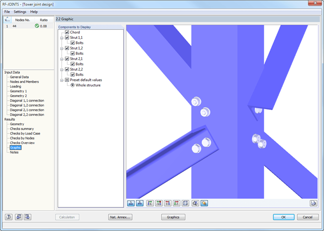
- Visualization of the entire connection in the view window
At first, the governing joint designs are arranged in groups and displayed with the basic geometry of the joint in the first result window. In the other result tables, you can see all fundamental design details such as the load-carrying capacity of anchors, stresses in welds, and others.
Dimensions, material specifications, and welds that are important for the construction of the connection are visible immediately and can be printed out. It is possible to visualize the connections in RF-/JOINTS Steel - Column Base or in the RFEM/RSTAB model.
All graphics can be included in the RFEM/RSTAB printout report or printed directly. Due to the scaled output, an optimal visual check is possible as early as in the design phase.
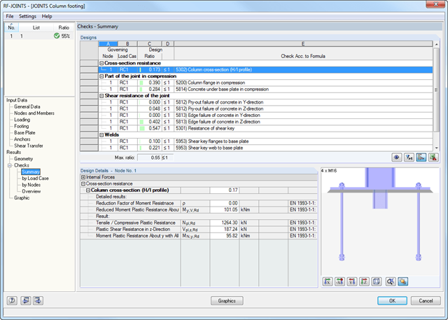
After the calculation, RF-/JOINTS Steel - Column Base displays the following design results:
- Base plate bending
- Anchor tension and anchor shear force
- Shear key strength
- Concrete compression / failure of concrete edges
- Friction
- Welds
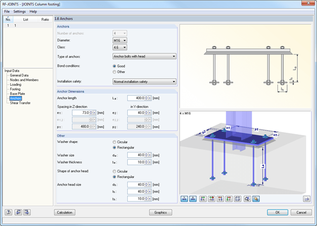
After you have selected the anchorage type and the design standard in the first input window, define the node in Window 1.2 that is to be imported from RFEM/RSTAB and where the footing anchorage is to be designed.
Optionally, you can define the column cross-section and material manually. In the next input windows, you can define the parameters of the base point, such as The loading is imported from RFEM/RSTAB or, in the case of a manual joint definition, the loads are entered.
All joint types are considered with the moment release at the column flange, or at the column web in the case of a rotated column. Therefore, the module determines the eccentric moment of a web cleat and fin plate connection, which additionally affects the bolt group at the girder flange.
Further eccentric moments may result from the locations of the angles and sheets. In the case of cleat connection, the forces are transferred separately. Shear forces act on the cleat; tension forces and stabilizing moment are assigned to the bolts. Before the calculation, the connection is checked for geometrical plausibility; for example, the bolt hole spacing and edge distance of the bolts.
All results can be evaluated and visualized in an appealing numerical and graphical form. Selection functions facilitate the targeted evaluation.
The printout report corresponds to the high standards of RFEM and -rstab RSTAB. Modifications are updated automatically. Furthermore, you can print the reduced report in a short form, including all relevant data and a user-defined cross-section graphic.
The design includes detailed information about analyzed internal forces, validity limits, and design conditions. Design failures are clearly marked in the result overview.
All input and result data are also documented in the general RFEM/RSTAB printout report. Separate design cases allow flexible analysis of the individual components in large structures.
A successful design check is based on the plausibility check of the geometric conditions.
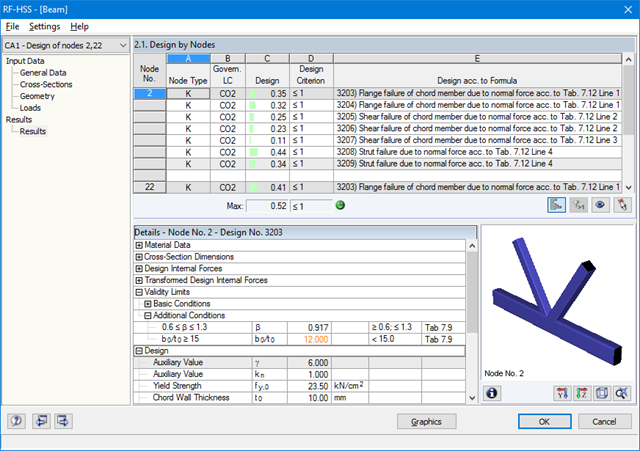
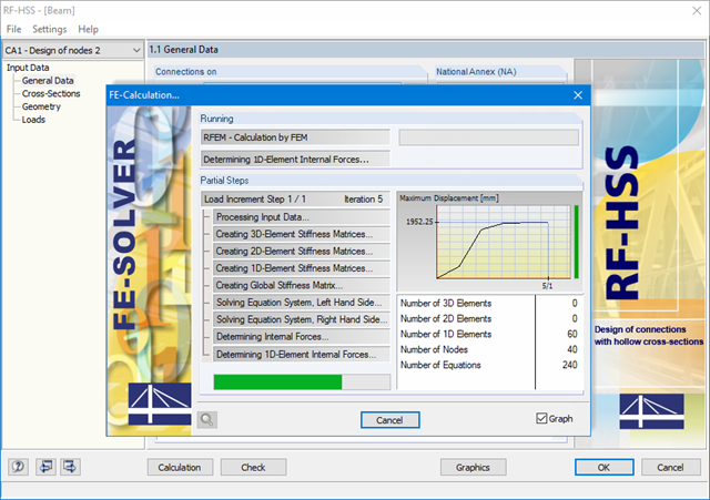
The RF-/HSS add-on module performs the calculation for the following designs:
- Flange failure of chord member due to normal force
- Shear failure of chord member due to normal force
- Strut failure due to normal force
- Punching shear due to normal force
- Integration in RFEM/RSTAB with automatic geometry recognition and transfer of internal forces
- Optional manual definition of connections
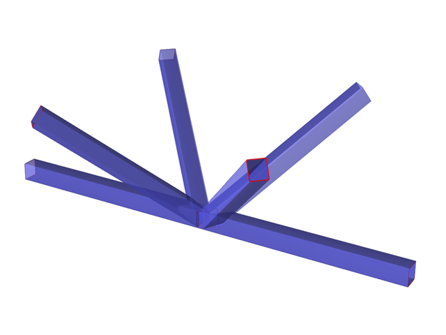
- Extensive library of hollow sections for chords and struts:
- Round sections
- Square sections
- Rectangular sections
- Implemented steel grades: S 235, S 275, S 355, S 420, S 450, and S 460
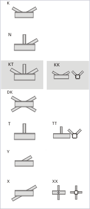
- Various types of connections available, depending on the standard specifications:
- K connection (gap/overlapping)
- KK connection (spatial)
- N connection (gap/overlapping)
- KT connection (gap/overlapping)
- DK connection (gap/overlapping)
- T connection (planar)
- TT connection (spatial)
- Y connection (planar)
- X connection (planar)
- XX connection (spatial)
- Selection of partial safety factors according to the National Annex for Germany, Austria, Czech Republic, Slovakia, Poland, Slovenia, Switzerland, or Denmark
- Adjustable angles between struts and chords
- Optional chord rotation of 90° for rectangular hollow sections
- Consideration of gaps between struts or overlapping struts
- Optional consideration of additional nodal forces
- Design of the connection as the maximum load-bearing capacity of the struts of a truss for axial forces and bending moments
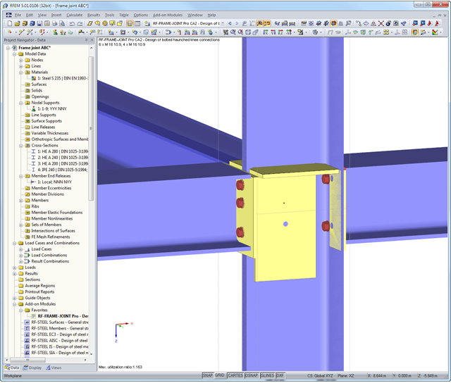
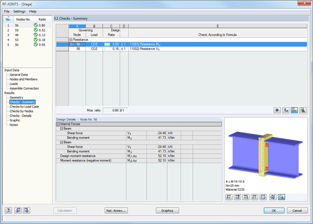
First, the module combines governing designs of the column and the horizontal beam and displays the connection geometry in a result table. The other result tables include all important design details such as flow line lengths, load-bearing capacity of screws, weld stresses, or connection stiffnesses. All connections are visualized in a 3D rendering graphic.
Dimensions, material specifications, and welds that are important for the construction of the connection are visible immediately and can be printed out. It is possible to visualize the connections in RF-/FRAME-JOINT Pro or directly in the RFEM/RSTAB model. All graphics can be included in the RFEM/RSTAB printout report or printed directly. Due to the scaled output, an optimal visual check is possible as early as in the design phase.
The RF-/FRAME-JOINT Pro add-on module performs the following designs according to the standards EN 1993-1-8 or DIN 18800:
- Beam end plate and column flange according to the plastic hinge theory
- Tension of bolts (including contact forces)
- Shearing of bolts
- Tension force introduction in column web and beam web
- Buckling analysis of gusset plate
- Shear design of gusset plate
- Compression force introduction in column web and buckling design of web plate
- If required:
- Design of diagonal stiffeners
- Web stiffener
- Supplementary web plates
- Compression force introduction in horizontal beam
- Design of welds
RF-CONCRETE Surfaces:
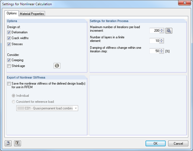
The nonlinear deformation analysis is performed by an iterative process considering the stiffness in cracked and non-cracked sections. The nonlinear reinforced concrete modeling requires definition of material properties varying across the surface thickness. Therefore, a finite element is divided into a certain number of steel and concrete layers in order to determine the cross-section depth.
The mean steel strengths used in the calculation are based on the 'Probabilistic Model Code' published by the JCSS technical committee. It is up to the user whether the steel strength is applied up to the ultimate tensile strength (increasing branch in the plastic area). Regarding material properties, it is possible to control the stress-strain diagram of the compressive and tensile strength. For the concrete compressive strength, you can select a parabolic or a parabolic-rectangular stress-strain diagram. On the tension side of the concrete, it is possible to deactivate the tensile strength as well as to apply a linear-elastic diagram, a diagram according to the CEB-FIB model code 90:1993, and concrete residual tensile strength considering the tension stiffening between the cracks.
Furthermore, you can specify which result values should be displayed after the nonlinear calculation at the serviceability limit state:
- Deformations (global, local based on non-/deformed system)
- Crack widths, depths, and spacing of the top and bottom sides in principal directions I and II
- Stresses of the concrete (stress and strain in principal direction I and II) and of the reinforcement (strain, area, profile, cover, and direction in each reinforcement direction)
RF-CONCRETE Members:
The nonlinear deformation analysis of beam structures is performed by an iterative process considering the stiffness in cracked and non-cracked sections. The material properties of concrete and reinforcing steel used in the nonlinear calculation are selected according to a limit state. The contribution of the concrete tensile strength between the cracks (tension stiffening) can be applied either by means of a modified stress-strain diagram of the reinforcing steel, or by applying a residual concrete tensile strength.
It is possible to select connection nodes graphically in the RFEM/RSTAB model. The relevant cross-section data and geometry are imported automatically. You can also define the parameters of hollow section connections manually. If necessary, you can modify the sections in the module.
The default angle between struts and chords can be modified as well. The geometric relation of the struts to each other is important for the correct choice of design. This relationship can be defined by specifying a gap between the struts or by overlapping them.
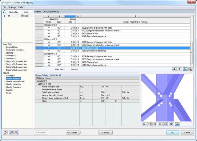
At first, the governing joint designs are arranged in groups and displayed with the basic geometry of the joint in the first result window. In the other result tables, you can see all fundamental design details such as the bearing resistance, shearing, sliding, and others.
Dimensions, material properties, and welds important for the connection construction are displayed immediately and can be printed directly. It is possible to visualize the connections in RF-/JOINTS Steel - Tower or in the RFEM/RSTAB model.
All graphics can be included in the RFEM/RSTAB printout report or printed directly. Due to the scaled output, an optimal visual check is possible as early as in the design phase.

- Design of knee joints, T-joints, cross joints, and continuous column connections with I-shaped sections
- Import of geometry and load data from RFEM/RSTAB or manual specification of the connection (for example, for recalculation without an existing RFEM/RSTAB model)
- Flush top connections or connections with bolt row in extension
- Design of positive and negative frame joint moments
- Various inclinations of right and left horizontal beams as well as application to frames of duopitch and monopitch roofs
- Consideration of additional flanges in a horizontal beam, for example for tapered sections
- Symmetrical and asymmetrical T-joints or cross joints
- Two-sided connection with different cross-section depth on the right and left
- Automatic preliminary design of bolt layout and required stiffening
- Optional design mode with possibility to specify all bolt spacing, welds, and sheet thicknesses
- Screwability check with adjustable dimensions of used wrenches
- Connection classification by stiffness and calculation of the spring stiffness of connections considered in the internal forces determination
- Check up to 45 individual designs (components) of the connection
- Automatic determination of governing internal forces for each individual design
- Controllable connection graphics in rendering mode with specifications of material, sheet thickness, welds, bolt spacing, and all dimensions for construction
- Integrated and flexibly extensible settings of National Annexes according to EN 1993-1-8 standard
- Automatic conversion of internal forces from structural analysis into respective sections, also for eccentric member connections
- Automatic determination of initial stiffness Sj,ini of the connection
- Detailed plausibility check of all dimensions, including specifications of input limits (for example, for edge distances and hole spacing)
- Optional application of compression forces to a column through contact
- Possibility to update the cross-section depth of horizontal beams in case of tapered connections after connection geometry optimization in RF-/FRAME-JOINT Pro
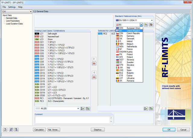
After selecting the loads required for the design and, if necessary, the desired standard for the design, you can define the limit loads in Window 1.2 Limit Parameters. In addition to the manufacturers listed in the limit library, it is possible to add user-defined entries.
After selecting all limit elements for the design, you can optionally define the load duration class (LDC). However, this module window is available only for timber fastener design according to EN 1995-1-1 or DIN 1052.
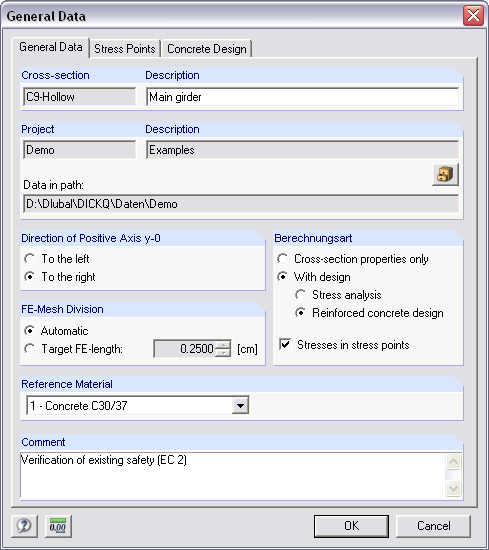
- Cross-section modeling using surfaces, openings, and point areas (reinforcements) limited by polygons
- Automatic or individual arrangement of stress points
- Extensible library of concrete, steel, and reinforcing steel materials
- Cross-section properties of reinforced concrete and composite cross-sections
- Stress analysis with yield hypothesis according to von Mises and Tresca
- Reinforced concrete design according to:
-
 DIN 1045-1:2008-08
 -
DIN 1045:1988-07
-
 ÖNORM B 4700: 2001-06-01
 -
 EN 1992-1-1:2004
-
- For the design according to EN 1992-1-1:2004, the following National Annexes are available:
-
DIN EN 1992-1-1/NA:2013-04 (Germany)
-
 NEN-EN 1992-1-1/NA:2011-11 (Netherlands)
 -
 CSN EN 1992-1-1/NA:2006-11 (Czech Republic)
 -
ÖNORM B 1992-1-1:2011-12 (Austria)
-
 UNE EN 1992-1-1/NA:2010-11 (Spain)
 -
 EN 1992-1-1 DK NA:2007-11 (Denmark)
 -
 SIST EN 1992-1-1:2005/A101:2006 (Slovenia)
 -
 NF EN 1992-1-1/NA:2007-03 (France)
 -
 STN EN 1992-1-1/NA:2008-06 (Slovakia)
 -
 SFS EN 1992-1-1/NA:2007-10 (Finland)
 -
 BS EN 1992-1-1:2004 (United Kingdom)
 -
 SS EN 1992-1-1/NA:2008-06 (Singapore)
 -
 NP EN 1992-1-1/NA:2010-02 (Portugal)
 -
 UNI EN 1992-1-1/NA:2007-07 (Italy)
 -
 SS EN 1992-1-1/NA:2008 (Sweden)
 -
 PN EN 1992-1-1/NA:2008-04 (Poland)
 -
 NBN EN 1992-1-1 ANB:2010 (Belgium)
 -
 NA to CYS EN 1992-1-1:2004/NA:2009 (Cyprus)
 -
 BDS EN 1992-1-1:2005/NA:2011 (Bulgaria)
 -
 LST EN 1992-1-1:2005/NA:2011 (Lithuania)
 -
 SR EN 1992-1-1:2004/NA:2008 (Romania)
-
- In addition to the National Annexes (NA) listed above, you can also define a specific NA, applying user‑defined limit values and parameters.
- Reinforced concrete design for stress-strain distribution, available safety, or direct design
- Results of reinforcement list and total reinforcement area
- Printout report with option to print a short form
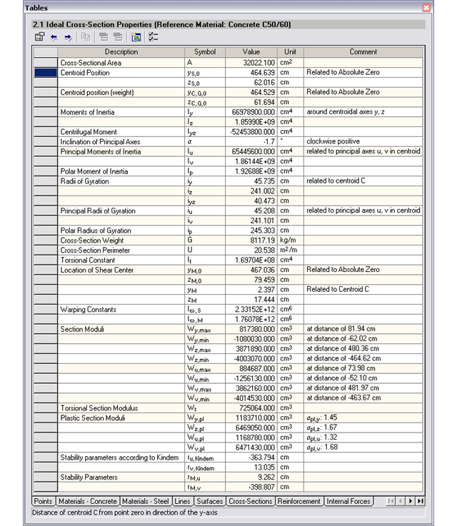
- Cross-sectional area A
- Shear areas Ay und Az with or without transversal shear
- Centroid position yS, zS
- moments of area 2 degrees Iy, Iz, Iyz, Iu, Iv, Ip
- Inclination of principal axes α
- Radii of gyration iy, iz, iyz, iu, iv, ip
- Torsional constant J
- Cross-section weight G and cross-section perimeter U
- Location of the shear center yM, zM
- Warping constants Iω,S, Iω,M
- Max/min cross-section moduli Sy, Sz, Su, Sv und St
- Plastic cross-section moduli Zy,pl, Zz,pl, Zu,pl, Zv,pl
- Stress function according to Prandtl φ
- Derivation of φ with respect to y and z
- Warping ω
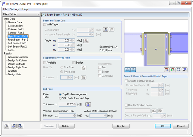
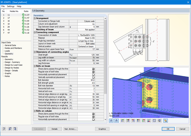
The RF-/FRAME-JOINT Pro add-on module designs connections of structures calculated in RFEM/RSTAB. If there is no RFEM/RSTAB structure available, you can define the geometry and loading manually; for example, when checking external calculations, for example.
Designed nodes are usually imported from RFEM/RSTAB. The module recognizes all connected members automatically and assigns a connection type to them. Depending on the connection type, you can define further details of ribs, backing plates, web plates, bolts, welds, and hole spacing. As loads, you can select any load case, load combination or result combination in RFEM/RSTAB.
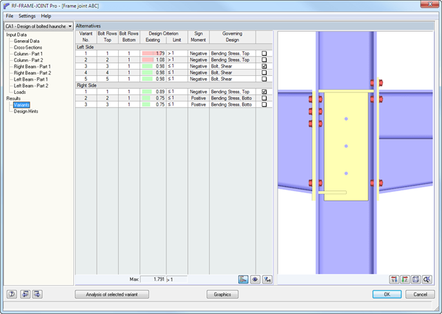
In the case of the "preliminary design" calculation mode, RF-/FRAME-JOINT Pro performs the first calculation step to suggest applicable layouts. After you select the relevant layout, the module displays all designs in detailed result tables and various graphics.
.png?mw=640&hash=c9c52de2eed98a2905a02fbf54b073f645c0df2c)
- Design of moment resistant and simple joints of I-shaped rolled cross-sections according to Eurocode 3:
- Moment-resisting end plate connections (type IH/IM)
- Moment resistant purlin splices (PM type)
- Simple joints with angle cleat and long angles (IW and IG types)
- Simple joints with header end plates mounted either on web only or on web and flange (IS type)
- Check of coped connections (IK) in combination with pinned end plates (IS) and angle connections (IW)
- Automatic design of required joint with bolt sizes (all types)
- Check of required thickness of load-bearing members for shear connections
- Results of all required structural details such as appliances, hole arrangements, necessary extensions, a number of bolts, end plate dimensions, and welds
- Results including stiffnesses Sj,ini of bending-resistant connections
- Documentation of available loading and comparison with resistances
- Results of design ratio for each individual joint
- Automatic determination of governing internal forces for several load cases and connection nodes
After the design, all results are displayed in clearly arranged result tables; for example, by load case or by node. The governing internal forces are compared with the limit values listed in the DSTV guideline.
You can visualize the joints graphically in the add-on module or in RFEM/RSTAB. In addition to the input and result data, including design details displayed in tables, you can add all graphics into the printout report. This way, comprehensible and clearly arranged documentation is guaranteed.