.png?mw=640&hash=53c64389797699e939283ddbfc3d88485fcbfbf5)
- Full integration in RFEM/RSTAB, including import of all relevant loads
- General stress analysis with warping torsion according to elastic-elastic method
- Stability analysis of planar continuous members for buckling and lateral-torsional buckling
- Determination of critical load factor and thus of Mcr or Ncr (the factor can be used in RF-/LTB for the el/pl design)
- Lateral-torsional buckling analysis of any cross-section (also the SHAPE-THIN cross-sections)
- Design of members and sets of members with applied torsion (for example, crane girder)
- Optional determination of the limit load factor (critical load factor)
- Display of eigenmodes and torsional modes on the rendered cross-section
- Wide range of tools for determining shear panels and rotational restraints (such as corrugated sheets, purlins, bracings)
- Easy determination of discrete springs such as warp springs from end plates or rotational springs from columns
- Graphical selection of load application points on a cross-section (upper chord, centroid, lower chord, or any other point)
- Free arrangement of eccentric nodal and line supports on a cross-section
- Determination of value for inclination or precamber by means of eigenvalue analysis
- Special warping releases applicable for definition of warping conditions on transitions
After the calculation, the deformations, internal forces, support forces, and stresses are displayed. Since the module considers warping torsion, the diagrams of the warping bimoment, as well as of the primary and the secondary torsional moment, are also available. Stability analysis uses the imperfections during the calculation and determines the critical load factors that can be used to determine Mki and Nki.
In addition to the result values in tables, the corresponding cross-section graphic is shown. In RFEM/RSTAB, various results are highlighted in different colors on the member model. You can modify the colors and values assigned.
Result diagrams of a set of members provide targeted evaluation. It is also possible to represent all intermediate values. Finally, it is possible to export all tables to MS Excel or in a CSV file. A dialog box includes the necessary export data.
Comprehensive and easy options in the individual input windows facilitate the representation of the structural system:
Nodal Supports
- The support type of each node is editable.
- It is possible to define a warp stiffening on each node. The resulting warp spring is determined automatically using the input parameters.
Elastic member foundation
- In the case of elastic member foundations, you can manually enter spring constants.
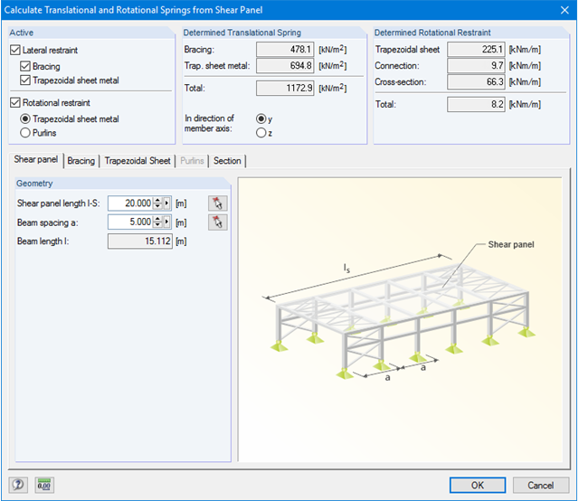
- Alternatively, you can use the various options to define the rotational and translational springs from a shear panel.
Member End Springs
- RF-/FE-LTB calculates the individual spring constants automatically. You can use the dialog boxes and detailed pictures to represent a translational spring by connecting component, a rotational spring by a connecting column, or a warping stiffener (available types: end plate, channel section, angle, connecting column, cantilevered portion).
Member Hinges
- If there are no member hinges defined in RFEM/RSTAB for the set of members, you can define them directly in the RF-/FE-LTB add-on module.
Load Data
- The nodal and member loads of the selected load cases and combinations are displayed in separate windows. There you can edit, delete, or add them individually.
Imperfections
- RF-/FE-LTB automatically applies the imperfections by scaling the lowest eigenvector.
The details for the lateral-torsional buckling analysis are defined separately for members and sets of members. The following parameters can be set:
Support Type/Lateral-Torsional Buckling Load
- Available options are Lateral and torsional restraint, Lateral and torsional restraint or Cantilever
- Special supports are possible by specifying the degree of restraint βz and the degree of warping restraint β0. In this section as well, you can consider the elastic warping restraint of an end plate, a channel section, an angle, a column connection, and a beam cantilever by specifying the geometry dimensions.
- As an alternative, it is also possible to enter the lateral-torsional buckling load NKi or the effective length sKi directly
Shear panel
- A shear panel can be defined from a trapezoidal sheeting, bracing, or a combination of these
- Alternatively, you can enter the shear panel stiffness Sprov directly
Rotational restraint
- Choose between continuous and discontinuous rotational restraint
Position of Positive Transverse Load Application
- The z-coordinate of the load application point can be freely selected in a detailed cross-section graphic. (upper chord, lower chord, centroid)
- Alternatively, you can specify the data by selecting them or entering the data manually.
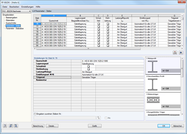
Beam Type
- For standard sections, the rolled beam, welded beam, castellated beam, notched beam, or tapered beam (web or flange welded) options are available
- For special cross-sections, it is possible to directly enter the beam factor n, the reduced beam factor n, or the reduction factor κM
Geometry, material, cross-section, action, and imperfection data are entered in clearly arranged input windows:
Geometry
- Quick and convenient data input
- Definition of support conditions based on various support types (hinged, hinged movable, rigid, and user-defined, as well as lateral on upper or bottom flange)
- Optional specification of warping restraint
- Variable arrangement of rigid and deformable support stiffeners
- Possibility to insert hinges
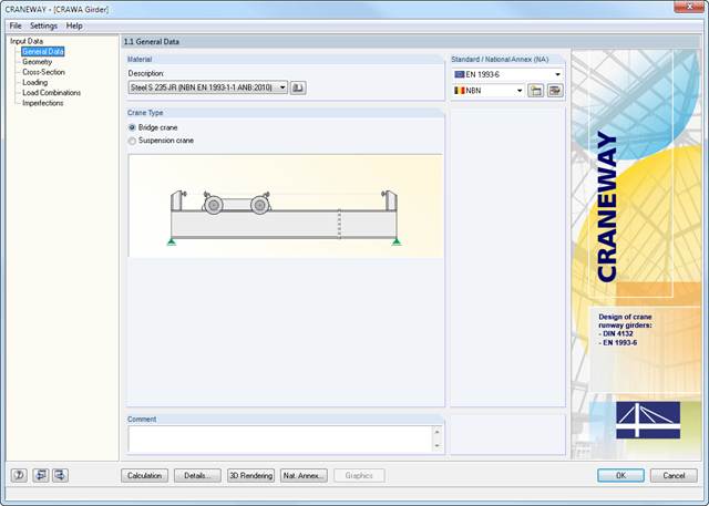
CRANEWAY Cross-Sections
- I-shaped rolled cross-sections (I, IPE, IPEa, IPEo, IPEv, HE-B, HE-A, HE-AA, HL, HE-M, HE, HD, HP, IPB-S, IPB-SB, W, UB, UC, and other cross-sections according to AISC, ARBED, British Steel, Gost, TU, JIS, YB, GB, and others) combinable with section stiffener on the upper flange (angles or channels) as well as rail (SA, SF) or splice with user-defined dimensions
- Unsymmetrical I-sections (type IU) also combinable with stiffeners on the upper flange as well as with rail or splice
Actions
It is possible to consider the actions of up to three simultaneously operated cranes. You can simply select a standard crane from the library. You can also enter data manually:
- Number of cranes and crane axles (maximum of 20 axles per crane), center distances, position of crane buffers
- Classification in damage classes with editable dynamic factors according to EN 1993-6, and in lifting classes and exposure categories according to DIN 4132
- Vertical and horizontal wheel loads from self-weight, hoist load, mass forces from drive, as well as loads from skewing
- Axial loading in driving direction as well as buffer forces with user-defined eccentricities
- Permanent and variable secondary loads with user-defined eccentricities
Imperfections
- The imperfection load applies in compliance with the first natural vibration mode - either identically for all load combinations to be designed, or individually for each load combination, as mode shapes may vary depending on the load.
- Convenient tools available for scaling the mode shapes (rise determination of inclination and precamber).
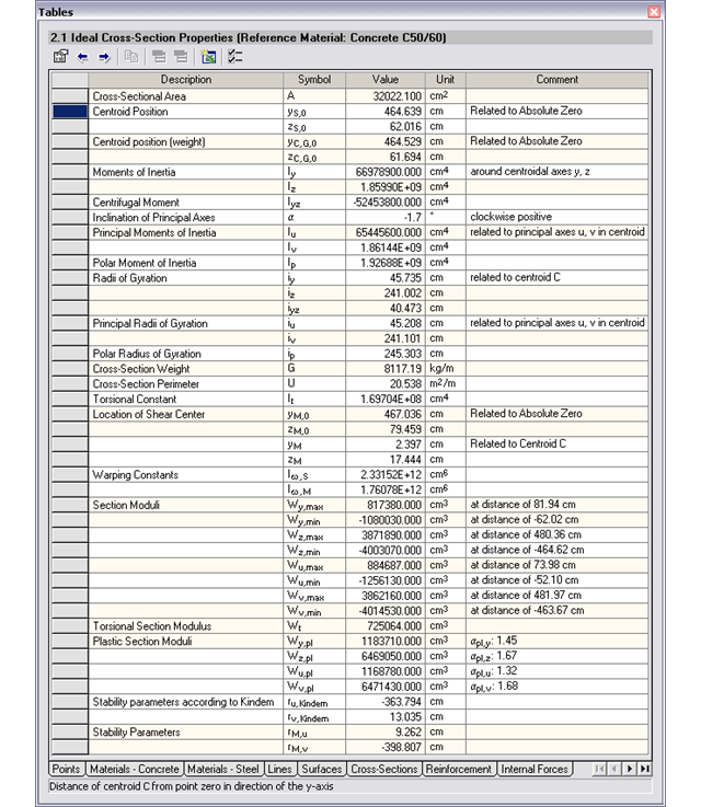
- Cross-sectional area A
- Shear areas Ay und Az with or without transversal shear
- Centroid position yS, zS
- moments of area 2 degrees Iy, Iz, Iyz, Iu, Iv, Ip
- Inclination of principal axes α
- Radii of gyration iy, iz, iyz, iu, iv, ip
- Torsional constant J
- Cross-section weight G and cross-section perimeter U
- Location of the shear center yM, zM
- Warping constants Iω,S, Iω,M
- Max/min cross-section moduli Sy, Sz, Su, Sv und St
- Plastic cross-section moduli Zy,pl, Zz,pl, Zu,pl, Zv,pl
- Stress function according to Prandtl φ
- Derivation of φ with respect to y and z
- Warping ω
The results of warping torsion analysis are displayed in RF-/STEEL AISC and RF-/STEEL EC3 in the usual way. Among other results, the corresponding result windows include the critical warping and torsional values, internal forces, and design summary.
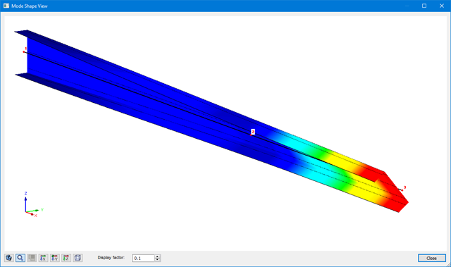
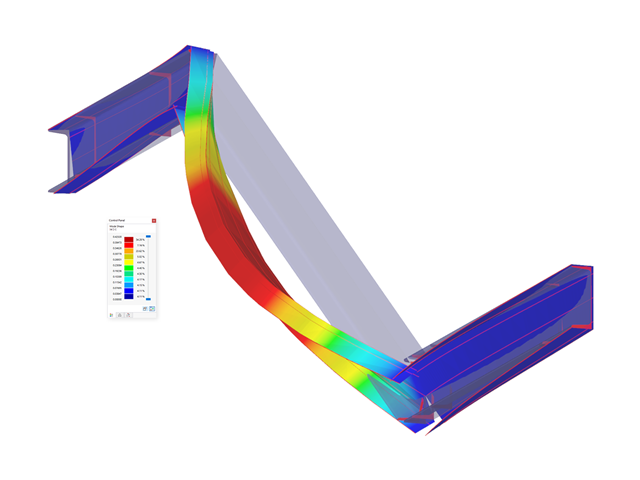
The graphical display of mode shapes (incl. warping) enables a realistic assessment of buckling behavior.
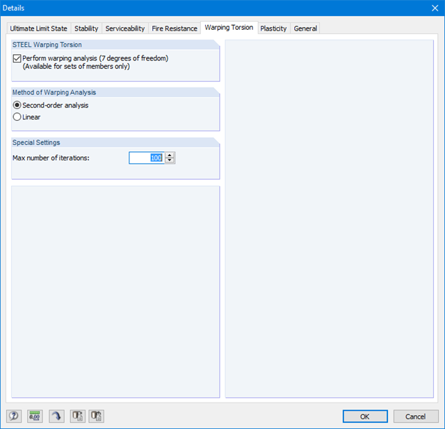
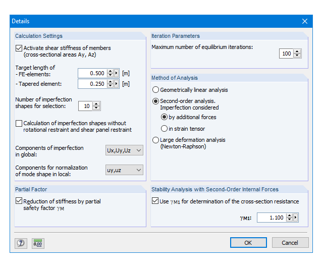
Since RF-/STEEL Warping Torsion is fully integrated in RF-/STEEL AISC and RF‑/STEEL EC3, the data are entered in the same way as for the usual design in these modules. It is only necessary to select the option "Perform warping analysis" in the Details dialog box, tab Warping Torsion (see the figure on the right). You can also define the maximum number of iterations in this dialog box.
The warping torsion analysis is performed for sets of members in RF-/STEEL AISC and RF‑/STEEL EC3. You can define boundary conditions such as nodal supports or member end releases for them.
It is also possible to specify imperfections for the nonlinear calculation.

SHAPE-THIN determines the section properties and stresses of any open, closed, built-up, or non-connected cross-sections.
- Section Properties
- Cross-sectional area A
- Shear areas Ay, Az, Au, and Av
- Centroid position yS, zS
- moments of area 2 degrees Iy, Iz, Iyz, Iu, Iv, Ip, Ip,M
- Radii of gyration iy, iz, iyz, iu, iv, ip, ip,M
- Inclination of principal axes α
- Cross-section weight G
- Cross-section perimeter U
- torsional constants of area degrees IT, IT,St.Venant, IT,Bredt, IT,s
- Location of the shear center yM, zM
- Warping constants Iω,S, Iω,M or Iω,D for lateral restraint
- Max/min section moduli Sy, Sz, Su, Sv, Sω,M with locations
- Section ranges ru, rv, rM,u, rM,v
- Reduction factor λM
- Plastic Cross-Section Properties
- Axial force Npl,d
- Shear forces Vpl,y,d, Vpl,z,d, Vpl,u,d, Vpl,v,d
- Bending moments Mpl,y,d, Mpl,z,d, Mpl,u,d, Mpl,v,d
- Section moduli Zy, Zz, Zu, Zv
- Shear areas Apl,y, Apl,z, Apl,u, Apl,v
- Position of area bisecting axes fu, fv,
- Display of the inertia ellipse
- First moments of area Qu, Qv, Qy, Qz with location of maxima and specification of shear flow
- Warping coordinates ωM
- moments of area (warping areas) Sω,M
- Cell areas Am of closed cross-sections
- Normal stresses σx due to axial force, bending moments, and warping bimoment
- Shear stresses τ from shear forces as well as primary and secondary torsional moments
- Equivalent stresses σv with customizable factor for shear stresses
- Stress ratios, related to limit stresses
- Stresses for element edges or center lines
- Weld stresses in fillet welds
- Section properties of non-connected cross-sections (cores of high-rise buildings, composite sections)
- Shear wall shear forces due to bending and torsion
- Plastic capacity design with determination of the enlargement factor αpl
- Check of the c/t-ratios following the design methods el-el, el-pl or pl-pl according to DIN 18800
- Full integration in the RF-/STEEL EC3 add‑on module
- Design of cross-sections for tension, compression, bending, torsion, shear, and combined internal forces
- Plastic design of members according to the second‑order analysis with 7 degrees of freedom, including warping torsion (requires module extension RF‑/STEEL Warping Torsion).
- Applicable for members defined as sets of members
- Separate solver that considers 7 deformation directions (ux, uy, uz, φx, φy, φz, ω) or 8 internal forces (N, Vu, Vv, Mt,pri, Mt,sec, Mu, Mv, Mω)
- Nonlinear design according to second-order analysis
- Input of imperfections
- Calculation of critical load factors and buckling mode shapes as well as the visualization of them (incl. warping)
- Integration into member design in the RF-/STEEL AISC and RF‑/STEEL EC3 add‑on modules
- Available for all thin‑walled steel cross‑sections

- Import of materials, cross-sections, and internal forces from RFEM/RSTAB
- Steel design of thin‑walled cross‑sections according to EN 1993‑1‑1:2005 and EN 1993‑1‑5:2006
- Automatic classification of cross-sections according to EN 1993-1-1:2005 + AC:2009, Cl. 5.5.2, and EN 1993-1-5:2006, Cl. 4.4 (cross-section class 4), with optional determination of effective widths according to Annex E for stresses under fy
- Integration of parameters for the following National Annexes:
-
 DIN EN 1993-1-1/NA:2015-08 (Germany)
 -
 ÖNORM B 1993-1-1:2007-02 (Austria)
 -
 NBN EN 1993-1-1/ANB:2010-12 (Belgium)
 -
 BDS EN 1993-1-1/NA:2008 (Bulgaria)
 -
 DS/EN 1993-1-1 DK NA:2015 (Denmark)
 -
 SFS EN 1993-1-1/NA:2005 (Finland)
 -
 NF EN 1993-1-1/NA:2007-05 (France)
 -
 ELOT EN 1993-1-1 (Greece)
 -
 UNI EN 1993-1-1/NA:2008 (Italy)
 -
 LST EN 1993-1-1/NA:2009-04 (Lithuania)
 -
 UNI EN 1993-1-1/NA:2011-02 (Italy)
 -
 MS EN 1993-1-1/NA:2010 (Malaysia)
 -
 NEN EN 1993-1-1/NA:2011-12 (Netherlands)
 - NS EN 1993-1-1/NA:2008-02 (Norway)
-
 PN EN 1993-1-1/NA:2006-06 (Poland)
 -
 NP EN 1993-1-1/NA:2010-03 (Portugal)
 -
 SR EN 1993-1-1/NB:2008-04 (Romania)
 -
 SS EN 1993-1-1/NA:2011-04 (Sweden)
 -
 SS EN 1993-1-1/NA:2010 (Singapore)
 -
 STN EN 1993-1-1/NA:2007-12 (Slovakia)
 -
 SIST EN 1993-1-1/A101:2006-03 (Slovenia)
 -
 UNE EN 1993-1-1/NA:2013-02 (Spain)
 -
 CSN EN 1993-1-1/NA:2007-05 (Czech Republic)
 -
 BS EN 1993-1-1/NA:2008-12 (the United Kingdom)
 -
 CYS EN 1993-1-1/NA:2009-03 (Cyprus)
 - In addition to the National Annexes (NA) listed above, you can also define a specific NA, applying user‑defined limit values and parameters.
- Automatic calculation of all required factors for the design value of flexural buckling resistance Nb,Rd
- Automatic determination of the ideal elastic critical moment Mcr for each member or set of members on every x-location according to the Eigenvalue Method or by comparing moment diagrams. You only have to define the lateral intermediate supports.
- Design of tapered members, unsymmetric sections or sets of members according to the General Method as described in EN 1993-1-1, Cl. 6.3.4
- In the case of the General Method according to Cl. 6.3.4, optional application of "European lateral-torsional buckling curve" according to Naumes, Strohmann, Ungermann, Sedlacek (Stahlbau 77 [2008], pp. 748‑761)
- Rotational restraints can be taken into account (trapezoidal sheeting and purlins)
- Optional consideration of shear panels (for example, trapezoidal sheeting and bracing)
- RF-/STEEL Warping Torsion module extension (license required) for stability analysis according to the second-order analysis as stress analysis including consideration of the 7th degree of freedom (warping)
- Module extension RF-/STEEL Plasticity (license required) for plastic analysis of cross‑sections according to Partial Internal Forces Method (PIFM) and Simplex Method for general cross‑sections (in connection with the RF‑/STEEL Warping Torsion module extension, it is possible to perform the plastic design according to the second‑order analysis)
- Module extension RF-/STEEL Cold-Formed Sections (license required) for ultimate and serviceability limit state designs for cold-formed steel members according to the EN 1993-1-3 and EN 1993-1-5 standards
- ULS design: Selection of fundamental or accidental design situations for each load case, load combination, or result combination
- SLS design: Selection of characteristic, frequent, or quasi-permanent design situations for each load case, load combination, or result combination
- Tension analysis with definable net cross-section areas for member start and end
- Weld designs of welded cross-sections
- Optional calculation of warp spring for nodal support on sets of members
- Graphic of design ratios on cross-section and in RFEM/RSTAB model
- Determination of governing internal forces
- Filter options for graphical results in RFEM/RSTAB
- Representation of design ratios and cross‑section classes in the rendered view
- Color scales in result windows
- Automatic cross-section optimization
- Transfer of optimized cross-sections to RFEM/RSTAB
- Parts lists and quantity surveying
- Direct data export to MS Excel
- Verifiable printout report
- Possibility to include the temperature curve in the report
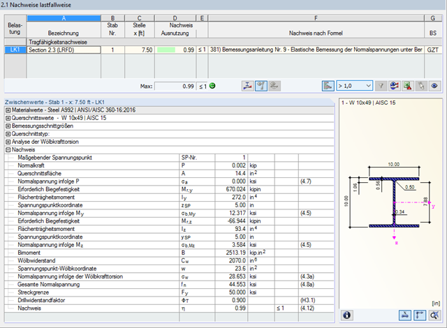
Due to the integrated RF-/STEEL Warping Torsion module extension, it is possible to perform the design according to Design Guide 9 in RF-/STEEL AISC.
The calculation is performed with 7 degrees of freedom according to the warping torsion theory and enables a realistic stability design, including consideration of torsion.
- Available for cold-formed L, Z, C, channel, top-hat, and CL sections from the cross-section database, as well as for general cold-formed (non-perforated) SHAPE-THIN-9 sections
- Determination of the effective cross-section considering the local buckling and the distortional buckling
- Cross-section ultimate limit state, stability, and serviceability limit state designs according to EN 1993‑1‑3
- Design of local transverse forces for webs without stiffening
- Available for all National Annexes included in RF-/STEEL EC3
- Module extension RF-/STEEL Warping Torsion (license required) for stability analysis according to second-order analysis as stress analysis including consideration of the 7th degree of freedom (warping)
.png?mw=640&hash=9aa98962d5e0d0ed2803b35fcb6a2f87288b0946)
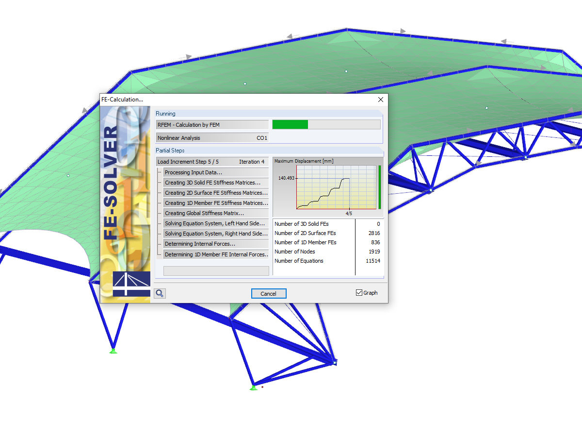
The number of degrees of freedom in a node is no longer a global calculation parameter in RFEM (6 degrees of freedom for each mesh node in 3D models, 7 degrees of freedom for the warping torsion analysis). Thus, each node is generally considered with a different number of degrees of freedom, which leads to a variable number of equations in the calculation.
This modification speeds up the calculation, especially for models where a significant reduction of the system could be achieved (for example, trusses and membrane structures).
- Consideration of 7 local deformation directions (ux, uy, uz, φx, φy, φz, ω) or 8 internal forces (N, Vu, Vv, Mt,pri, Mt,sec, Mu, Mv, Mω) when calculating member elements
- Usable in combination with a structural analysis according to linear static, second-order, and large deformation analysis (imperfections can also be taken into account)
- In combination with the Stability Analysis add-on, allows you to determine critical load factors and mode shapes of stability problems such as torsional buckling and lateral-torsional buckling
- Consideration of end plates and transverse stiffeners as warping springs when calculating I-sections with automatic determination and graphical display of the warping spring stiffness
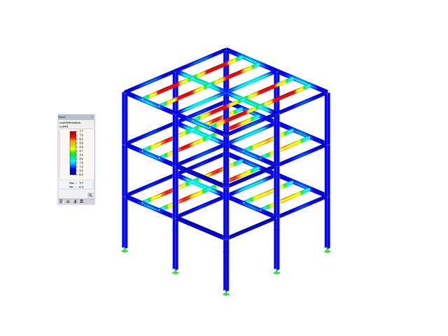
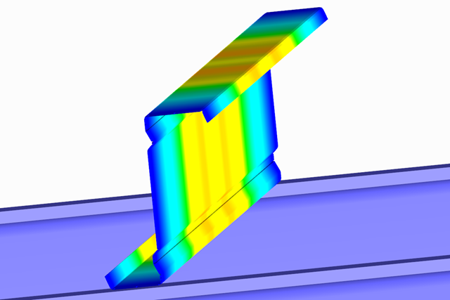
- Graphical display of the cross-section warping of members in the deformation
- Full integration with RFEM and RSTAB

You can perform the calculation of the warping torsion on the entire system. Thus, you consider the additional 7th degree of freedom in the member calculation. The stiffnesses of the connected structural elements are automatically taken into account. It means, you don't need to define equivalent spring stiffnesses or support conditions for a detached system.
You can then use the internal forces from the calculation with warping torsion in the add-ons for the design. Consider the warping bimoment and the secondary torsional moment, depending on the material and the selected standard. A typical application is the stability analysis according to the second-order theory with imperfections in steel structures.
Did you know that The application is not limited to thin-walled steel cross-sections. Thus, it is possible for you, for example, to perform the calculation of the ideal overturning moment of beams with solid timber cross-sections.

- You can activate or deactivate the use of torsional warping in the Add-ons tab of the model's Base Data.
- After activating the add-on, the user interface in RFEM is extended by some new entries in the navigator, tables, and dialog boxes.

- Design of tension, compression, bending, shear, torsion, and combined internal forces
- Tension design with consideration of a reduced section area (for example, hole weakening)
- Automatic classification of cross-sections to check local buckling
- Internal forces from the calculation with Torsional Warping (7 DOF) are taken into account by means of the equivalent stress check (currently not for the design standards AISC 360‑16 and GB 50017).
- Design of cross-sections of Class 4 with effective cross-section properties according to EN 1993‑1‑3 (licenses for RSECTION and Effective Sections are required for the RSECTION cross-sections)
- Shear buckling check according to EN 1993‑1‑5 with consideration of transverse stiffeners
- Design of stainless steel components according to EN 1993‑1‑4

- Stability analyses for flexural buckling, torsional buckling, and flexural-torsional buckling under compression
- Import of the effective lengths from the calculation using the Structure Stability add-on
- Graphical input and check of the defined nodal supports and effective lengths for stability analysis
- Lateral-torsional buckling analysis of the structural components subjected to moment loading
- Depending on the standard, a choice between user-defined input of Mcr, analytical method from the standard, and use of internal eigenvalue solver
- Consideration of a shear panel and a rotational restraint when using the eigenvalue solver
- Graphical display of a mode shape if the eigenvalue solver was used
- Stability analysis of structural components with the combined compression and bending stress, depending on the design standard
- Comprehensible calculation of all necessary coefficients, such as the factors for considering moment distribution or interaction factors
- Alternative consideration of all effects for the stability analysis when determining internal forces in RFEM/RSTAB (second-order analysis, imperfections, stiffness reduction, possibly in combination with the Torsional Warping (7 DOF) add-on)