
Get a better understanding of the stress distribution within member cross-sections using clipping planes.

The seismic design result is categorized into two sections: member requirements and connection requirements.
The "Seismic Requirements" include the Required Flexural Strength and the Required Shear Strength of the beam-to-column connection for moment frames. They are listed in the ‘Moment Frame Connection by Member’ tab. For braced frames, the Required Connection Tensile Strength and the Required Connection Compressive Strength of the brace are listed in the ‘Brace Connection by Member’ tab.
The program provides the performed design checks in tables. The design check details clearly display the formulas and references to the standard.
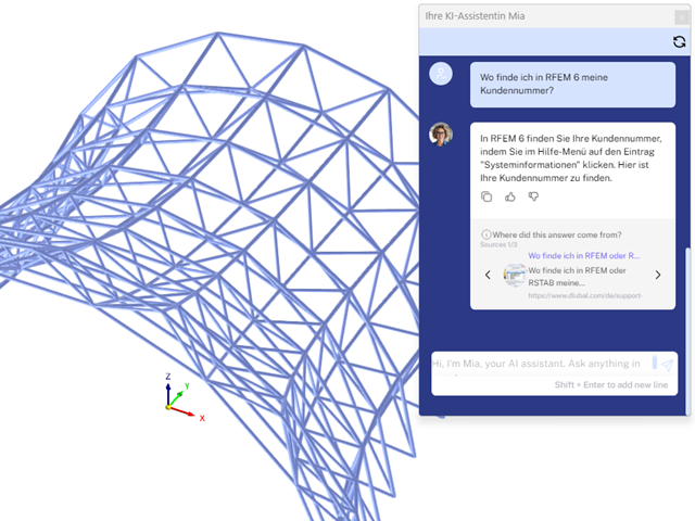
Mia is accessible in the programs and prevents the hassle of following up by email or phone.

Using the "Damper" member type, you can define a damping coefficient, a spring constant, and a mass. This member type extends the possibilities within the Time History Analysis.
With regard to viscoelasticity, the "Damper" member type is similar to the Kelvin-Voigt model, which consists of the damping element and an elastic spring (both connected in parallel).

The building model is calculated in two phases:
- Global 3D calculation of the global model, where the slabs are modeled as a rigid plane (diaphragm) or as a bending plate
- Local 2D calculation of the individual floors
After the calculation, the results of the columns and walls from the 3D calculation and the results of the slabs from the 2D calculation are combined in a single model. This means that there is no need to switch between the 3D model and the individual 2D models of the slabs. The user only works with one model, saves valuable time, and avoids possible errors in the manual data exchange between the 3D model and the individual 2D ceiling models.
The vertical surfaces in the model can be divided into shear walls and opening lintels. The program automatically generates internal result members from these wall objects, so they can be designed as members according to any standard in the Concrete Design add-on.

You have the option to perform the fire resistance design of surfaces using the reduced cross-section method. The reduction is applied over the surface thickness. It is possible to perform the design checks for all timber materials allowed for the design.
For cross-laminated timber, depending on the type of adhesive, you can select whether it is possible for individual carbonized layer parts to fall off, and whether you can expect increased charring in certain layer areas.

In RFEM 6 and RSTAB 9, you can export line graphics to the SVG format (vector graphics).
SVG stands for Scalable Vector Graphics and is an XML-based file format for displaying two-dimensional vector graphics. These vector graphics can be scaled without loss. It is possible to edit the SVG files using text editors, embed them on websites, and open them in the usual browsers.

The Concrete Design add-on provides you with the option to perform the simplified fire resistance design according to EN 1992‑1‑2 for columns (Section 5.3.2) and beams (Section 5.6).
The following design checks are available for the simplified fire resistance design:
- Columns: Minimum cross-sectional dimensions for rectangular and circular sections according to Table 5.2a as well as Equation 5.7 for calculating time of fire exposure
- Beams: Minimum dimensions and center distances according to Table 5.5 and Table 5.6
You can determine the internal forces for the fire resistance design according to two methods.
- 1 Here, the internal forces of the accidental design situation are included directly into the design.
- 2 The internal forces of the design at normal temperature are reduced by the factor Eta,fi (ηfi), then used in the fire resistance design.
Furthermore, it is possible to modify the axis distance according to Eq. 5.5.

Within the "Plastic capacity design | Simplex Method" in RSECTION, the simultaneous variation of shear stresses over the cross-sectional area is performed in addition to the variation of axial stresses. This extended form of analysis allows you to use redistribution reserves, especially for the cross-sections subjected to shear loading, thus loading the cross-sections even more efficiently.
Go to Explanatory Video
In the design add-ons (such as Steel Design, Timber Design, and so on), you can optimize cross-sections.
The optimization can be performed, for example, for standard cross-sections of a series, or for the width, height, and so on, in the case of parametric cross-sections.
Go to Explanatory Video
The Steel Joints add-on provides you with the option to connect circular hollow sections using welds.
It is possible to connect the circular sections to each other or to planar structural components. The fillets of standard and thin-walled sections can also be connected with a weld.
Go to Explanatory Video
Would you like to calculate curved beams (for example, made of glued-laminated timber)? For this purpose, you can use various section distributions for members:
- Curved
- Pitched cambered beam with constant height
- Pitched cambered beam with variable height
- Fish beam | Parabolic

In the "Steel Joints" add-on, you can consider preloaded bolts in all components during the calculation. You can easily activate the preloading using the check box in the bolt parameters, and it has an impact on the stress-strain analysis as well as the stiffness analysis.
Preloaded bolts are special bolts used in steel structures to generate a high clamping force between the connected structural components. This clamping force causes friction between the structural components, which allows for the transfer of forces.
Functionality
Preloaded bolts are tightened with a certain torque, causing them to stretch and generate a tensile force. This tensile force is transferred to the connected components and leads to a high clamping force. The clamping force prevents the connection from loosening and ensures safe force transmission.
Advantages
- High load-bearing capacity: Preloaded bolts can transfer large forces.
- Low deformation: They minimize the deformation of the connection.
- Fatigue strength: They are resistant to fatigue.
- Easy assembly: They are relatively easy to assemble and disassemble.
Analysis and Design
The calculation of preloaded bolts is performed in RFEM using the FE analysis model generated by the "Steel Joints" add-on. It takes into account the clamping force, friction between structural components, shear strength of bolts, and load-bearing capacity of the structural components. The design is carried out according to DIN EN 1993‑1‑8 (Eurocode 3) or the US standard ANSI/AISC 360‑16. You can save the created analysis model, including the results, and use it as an independent RFEM model.

You can display the RWIND results directly in the main program. In the Navigator - Results, select the Wind Simulation Analysis result type from the list above.
Currently, the following results are available, which refer to the RWIND computational mesh:
- Surface pressure
- Surface cp coefficient
- Wall distance y+ (steady flow)

You can import STEP files into RFEM 6. The data are directly converted into the native RFEM model data.
STEP is an interface standard initiated by ISO (ISO 10303). In the geometry description, all shapes relevant for RFEM (line, surface, and solid models) can be integrated by the CAD data models.
Note: This format is not to be confused with DSTV interfaces, which also use the file extension *.stp.

For design supports, you can take into account a shear force reduction. This allows you to perform the shear design with the governing shear force at a distance of the beam height from the support edge.

Did you know? In the Design Supports, you can now define fully threaded screws as transversal compression stiffening elements for the "Compression Perpendicular to Grain" design. In this case, the pressing-in and buckling of the bolts is analyzed.
Moreover, the design shear resistance is checked in the plane of the screw tip. The angle of dispersal can be considered as linear under 45° or nonlinear (according to Bejtka, I. (2005). Verstärkung von Bauteilen aus holz mit vollgewindeschrauben. KIT Scientific Publishing.).

The pushover analysis is managed by a newly introduced analysis type in the load combinations. Here, you have access to the selection of the horizontal load distribution and direction, the selection of a constant load, the selection of the desired response spectrum for the determination of the target displacement, and the pushover analysis settings tailored to the pushover analysis.
In the pushover analysis settings, you can modify the increment of the increasing horizontal load and specify the stopping condition for the analysis. Furthermore, it is possible to easily adjust the precision for the iterative determination of the target displacement.

- Consideration of nonlinear component behavior using plastic standard hinges for steel (FEMA 356, EN 1998‑3) and nonlinear material behavior (masonry, steel - bilinear, user-defined working curves)
- Direct import of masses from load cases or combinations for the application of constant vertical loads
- User-defined specifications for the consideration of horizontal loads (standardized to a mode shape or uniformly distributed over the height of the masses)
- Determination of a pushover curve with selectable limit criterion of the calculation (a collapse or limit deformation)
- Transformation of the pushover curve into the capacity spectrum (ADRS format, single degree of freedom system)
- Bilinearization of the capacity spectrum according to EN 1998‑1:2010 + A1:2013
- Transformation of the applied response spectrum into the required spectrum (ADRS format)
- Determination of target displacement according to EC 8 (the N2 method according to Fajfar 2000)
- Graphical comparison of the capacity and required spectrum
- Graphical evaluation of the acceptance criteria of predefined plastic hinges
- Result display of the values used in the iterative calculation of the target displacement
- Access to all results of the structural analysis in the individual load levels

The design of cold-formed steel members according to the AISI S100-16 / CSA S136-16 is available in RFEM 6. Design can be accessed by selecting “AISC 360” or “CSA S16” as the standard in the Steel Design Add-on. “AISI S100” or “CSA S136” is then automatically selected for the cold-formed design.
RFEM applies the Direct Strength Method (DSM) to calculate the elastic buckling load of the member. The Direct Strength Method offers two types of solutions, numerical (Finite Strip Method) and analytical (Specification). The FSM signature curve and buckling shapes can be viewed under Sections.

In the Steel Joints add-on, you can design connections according to the American standard ANSI/AISC 360‑16. The following design procedures are integrated:
- Load and Resistance Factor Design (LRFD)
- Allowable Stress Design (ASD)

For timber surfaces with the "Constant" thickness type, the crack factor kcr and thus the negative influence of cracks on the shear capacity is taken into account.

The new steel sections according to the latest CISC Handbook (12th edition) are available in RFEM 6. The sections are listed in the Standardized library. In the filter, select “Canada” for the region and “CISC 12” for the standard. Alternatively, the section name can be directly entered in the search box located at the bottom of the dialog box.

To determine the shear resistance of bolts, you can use the Steel Joints add-on to specify whether there is a shaft or a thread in the shear plane.
Go to Explanatory Video
In the Timber Design add-on for RFEM, you can design members as well as surfaces according to Eurocode 5, SIA 265 (Swiss standard), CSA O86 (Canadian standard), or ANSI/AWC NDS (American standard); for example, cross-laminated timber, glued-laminated timber, softwood, mass timber, and so on.
Go to Explanatory Video
Use RWIND 2 Pro to easily apply a permeability to a surface. All you need is the definition of
- the Darcy coefficient D,
- the inertial coefficient I, and
- the length of the porous medium in the direction of flow L,
to define a pressure boundary condition between the front and back of a porous zone. Due to this setting, you obtain the flow through this zone with a two-part result display on both sides of the zone area.
But that's not all. Furthermore, the generation of a simplified model recognizes permeable zones and takes into account the corresponding openings in the model coating. Can you waive an elaborate geometric modeling of the porous element? Understandable – we have good news for you then! With a pure definition of the permeability parameters, you can avoid complex geometric modeling of the porous element. Use this feature to simulate permeable scaffolding, dust curtains, mesh structures, and so on.
More Information
Do you already know the editor for mesh refinement control? It is a great help for your work! Why? It's easy – it gives you the following options:
- Graphic visualization of the areas with mesh refinements
- Mesh refinement of zones
- Deactivating the standard 3D solid mesh refinement with transversion into the corresponding manual 3D mesh refinements.
These options help you to formulate a suitable rule for meshing the entire model, even for the models with unusual dimensions. Use the editor to efficiently define small model details on large buildings or detailed meshing areas in the coating area of the model. You will be amazed!

Is there torsion? In this case, you can decide how to perform the design. You have the following options:
- Allow further design if shear stress due to torsion does not exceed limit value
- Design according to Timber Construction Manual, 4.6
- Ignoring torsion

The Aluminum Design add-on provides you with further options. Here you can also design general cross-sections that are not predefined in the cross-section library. For example, create a cross-section in the RSECTION program and then import it into RFEM/RSTAB. Depending on the design standard used, you can select from various design formats. This includes, for example, the equivalent stress analysis.
With a license for RSECTION and Effective Sections, you can also perform the design checks while taking into account the effective cross-section properties according to EN 1993‑1‑5.

The Torsional Warping (7 DOF) add-on allows you to perform the calculation of member structures in RFEM and RSTAB, taking into account the cross-section warping. You can consider all internal forces (N, Vu, Vv, Mt,pri, Mt,sec, Mu, Mv, Mω) determined in this way in the equivalent stress analysis of the aluminum design. Please Note: This feature is not yet available for the design standard ADM 2020.