37 Wyniki
Wyświetl wyniki:
Sortuj według:

Niniejszy artykuł dotyczy długotrwałego ugięcia konstrukcji betonowych zgodnie z ACI 318 i CSA A23.3.

Podczas obliczania regularnych konstrukcji wprowadzanie danych często nie jest skomplikowane, ale czasochłonne. Oszczędzaj cenny czas dzięki automatycznemu wprowadzaniu danych. W niniejszym przypadku należy uwzględnić kondygnacje domu jako poszczególne etapy budowy. Dane są wprowadzane przy pomocy programu w języku C#, aby użytkownik nie musiał ręcznie wprowadzać elementów poszczególnych pięter.

W tym artykule wyjaśniono różne metody dostępne w rozszerzeniu Analiza modalna, służące do określania liczby postaci własnych.

W tym artykule pokażemy, jak zdefiniować żebra podłużne na blasze pręta za pomocą komponentu „Żebro” w rozszerzeniu Połączenia stalowe.

Z tego artykułu dowiesz się, jak zamodelować proste połączenie z blachą czołową w programie RFEM 6.

Ocena przemieszczenia kondygnacji w budynku jest kluczowa dla zapewnienia zadowalających parametrów konstrukcyjnych poprzez ograniczenie przemieszczenia kondygnacji. Nadmierne znoszenie może powodować niestateczność systemu i powodować uszkodzenia elementów niekonstrukcyjnych, takich jak ściany działowe. W tym artykule opisano procedurę wyznaczania przemieszczeń międzykondygnacyjnych zgodnie z ASCE 7-22 i rozszerzeniem Model budynku w programie RFEM 6.

Zrozumienie sztywności połączeń stalowych ma kluczowe znaczenie w projektowaniu konstrukcji. Często połączenia są traktowane jako połączenia całkowicie sztywne lub przegubowe, co może prowadzić do nieekonomicznych lub nawet ryzykownych warunków projektowych. Dowiedz się, w jaki sposób program RFEM firmy Dlubal i rozszerzenie Połączenia stalowe pomagają weryfikować sztywność połączeń i nośność na zginanie, zapewniając bezpieczniejsze i bardziej ekonomiczne warunki projektowe.

Norma ASCE 7-22 [1], rozdz. 12.9.1.6 określa, kiedy efekty P-delta powinny być uwzględniane podczas przeprowadzania analizy modalnego spektrum odpowiedzi dla obliczeń sejsmicznych. W NBC 2020 [2], Wys. 4.1.8.3.8.c jedynie w niewielkim stopniu wymaga uwzględnienia przechyłów spowodowanych interakcją obciążeń grawitacyjnych z konstrukcją odkształconą. Z tego względu podczas przeprowadzania analizy sejsmicznej mogą wystąpić sytuacje, w których efekty drugiego rzędu, znane również jako P-delta, muszą zostać uwzględnione.

W artykule przedstawiono podstawowe pojęcia z zakresu dynamiki konstrukcji i ich roli w projektowaniu konstrukcji sejsmicznych. Duży nacisk kładzie się na wyjaśnienie aspektów technicznych w zrozumiały sposób, aby tematyka była zrozumiała dla czytelników bez dużej wiedzy technicznej.

Artykuł 4.1.8.7 kanadyjskich przepisów budowlanych (NBC) 2020 zawiera jasną procedurę dotyczącą metod analizy trzęsień ziemi. Metoda bardziej zaawansowana, a mianowicie metoda analizy dynamicznej opisana w rozdziale 4.1.8.12, powinna być stosowana dla wszystkich typów konstrukcji, z wyjątkiem tych, które spełniają kryteria podane w 4.1.8.7. W przypadku pozostałych konstrukcji, może być stosowana nieco prostsza metoda równoważnych sił statycznych (ESFP), opisana w rozdziale 4.1.8.11.

Obliczenia ze względu na zmęczenie zgodnie z EN 1992-1-1 należy przeprowadzać w przypadku elementów konstrukcyjnych, które są poddane działaniu dużych zakresów naprężeń i/lub wielu zmianom obciążenia. W takim przypadku obliczenia dla betonu i zbrojenia są przeprowadzane osobno. Dostępne są dwie alternatywne metody obliczeniowe.

W tym artykule wyjaśniono, jak działają obliczenia podczas wstępnej analizy sztywności w programie Połączenia stalowe.

Aby ocenić, czy w obliczeniach dynamicznych konieczne jest również uwzględnienie analizy drugiego rzędu, w normie EN 1998‑1, sekcje 2.2.2 i 4.4.2.2 zawarto współczynnik wrażliwości międzykondygnacyjnego znoszenia θ. Można ją obliczyć i przeanalizować za pomocą programów RFEM 6 i RSTAB 9.
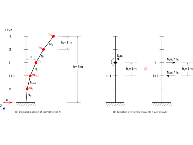
Zgodnie z normami EN 1998-1 sekcje 2.2.2 i 4.4.2.2 do obliczeń stanu granicznego nośności należy przeprowadzić obliczenia z uwzględnieniem teorii drugiego rzędu (efekt P-Δ). Efekt ten nie musi być uwzględniany tylko w przypadku, gdy współczynnik wrażliwości międzykondygnacyjnej jest mniejszy niż 0,1.

W tym artykule opisano na przykładzie płyty z betonu włóknistego, które wpływają na zastosowanie różnych metod całkowania i różnej liczby punktów całkowania na wynik obliczeń.
![Rozpiętości na podstawie Rysunku 5.2 z [1]](/pl/webimage/039540/3493372/01_Abmessungen_EN.png?mw=640&hash=a3c436931baff3514db261b2d11bfa39abae9170)
Aby poprawnie zwymiarować dźwigar lub belkę teową w programie RFEM 6 i w module dodatkowym 'Wymiarowanie betonu', ważne jest określenie 'szerokości pasów' prętów żebrowych. W tym artykule omówiono opcje wprowadzania danych dla belki dwuprzęsłowej oraz obliczanie wymiarów pasów zgodnie z EN 1992-1-1.

W tym artykule przedstawiono model połączenia zakładkowego płatwi ZL na dachu jednospadowym, obliczony w rozszerzeniu Połączenia stalowe i porównany z tabelą nośności podaną przez producenta.

Zarówno analiza drgań własnych, jak i analiza spektrum odpowiedzi przeprowadzane są na układzie liniowym. Jeżeli w modelu występują nieliniowości, podlega on linearyzacji, dzięki czemu elementy nieliniowe nie są brane pod uwagę w dalszej analizie. Mogą to być na przykład pręty rozciągane, podpory nieliniowe lub przeguby nieliniowe. W tym artykule pokazano, w jaki sposób można nimi zarządzać w analizie dynamicznej.
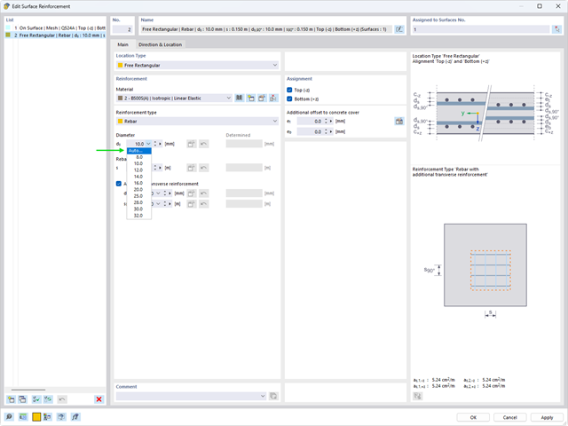
Automatyczny proces wymiarowania zbrojenia określa zbrojenie powierzchniowe, które zapewnia wymaganą ilość zbrojenia wynikającego z obliczeń.

Jeżeli, na przykład, do określenia sił wewnętrznych ma zostać zastosowany model czysto powierzchniowy, ale wymiarowanie komponentu nadal odbywa się na modelu prętowym, można skorzystać z belki wynikowej.