13 Wyniki
Wyświetl wyniki:
Sortuj według:

Analiza modalna jest punktem wyjścia do analizy dynamicznej układów konstrukcyjnych. Można ją wykorzystać do określenia wartości drgań własnych, takich jak częstotliwości drgań własnych, kształty drgań własnych, masy modalne i efektywne współczynniki masy modalnej. Wynik ten może zostać wykorzystany do obliczeń drgań oraz do dalszych analiz dynamicznych (na przykład obciążenia widmem odpowiedzi).

Analiza sejsmiczna w programie RFEM 6 jest możliwa przy użyciu rozszerzeń analizy modalnej i analizy spektrum odpowiedzi. Ogólna koncepcja analizy sejsmicznej w programie RFEM 6 opiera się na utworzeniu przypadku obciążenia do analizy modalnej lub analizy spektrum odpowiedzi. Grupy norm dla tych analiz są ustawiane w zakładce Normy II w oknie Dane podstawowe modelu.
Rozszerzenie Analiza etapów budowy (CSA) umożliwia wymiarowanie konstrukcji prętowych, powierzchniowych i bryłowych w programie RFEM 6 z uwzględnieniem określonych etapów budowy związanych z procesem konstrukcyjnym. Jest to o tyle istotne, że budynki nie powstają w całości od razu, lecz poprzez stopniowe łączenie poszczególnych części konstrukcyjnych. Poszczególne kroki, w których elementy konstrukcyjne oraz obciążenia są dodawane do budynku, nazywane są etapami budowy, podczas gdy sam proces budowy nazywa się procesem konstrukcyjnym.
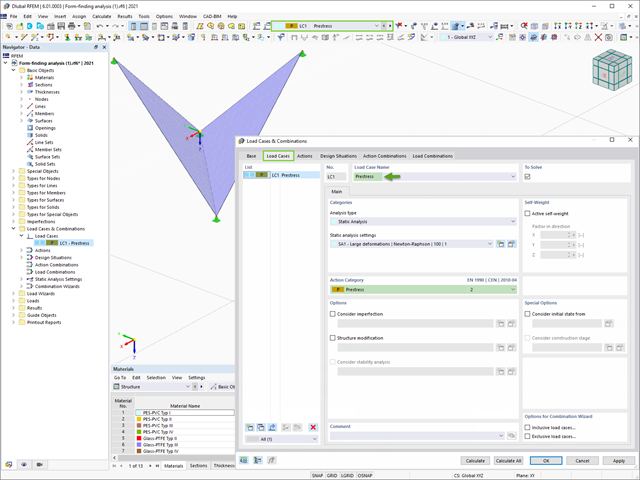
Program RFEM 6 zawiera rozszerzenie Form-Finding do określania kształtów równowagi modeli powierzchni obciążonych rozciąganiem i prętów obciążonych siłami osiowymi. Aktywuj ten dodatek w Danych bazowych modelu i użyj go, aby znaleźć położenie geometryczne, w którym naprężenie wstępne lekkich konstrukcji jest w równowadze z istniejącymi warunkami brzegowymi.

Analiza dynamiczna w RFEM 6 i RSTAB 9 jest podzielona na kilka rozszerzeń. Rozszerzenie Analiza modalna jest niezbędne dla wszystkich innych rozszerzeń do analizy dynamicznej, ponieważ przeprowadza analizę drgań własnych dla modeli prętów, powierzchni i brył.

W artykule przedstawiono podstawowe pojęcia z zakresu dynamiki konstrukcji i ich roli w projektowaniu konstrukcji sejsmicznych. Duży nacisk kładzie się na wyjaśnienie aspektów technicznych w zrozumiały sposób, aby tematyka była zrozumiała dla czytelników bez dużej wiedzy technicznej.

W tym artykule wyjaśniono różne metody dostępne w rozszerzeniu Analiza modalna, służące do określania liczby postaci własnych.

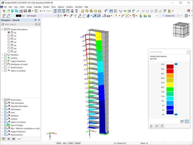
Ocena przemieszczenia kondygnacji w budynku jest kluczowa dla zapewnienia zadowalających parametrów konstrukcyjnych poprzez ograniczenie przemieszczenia kondygnacji. Nadmierne znoszenie może powodować niestateczność systemu i powodować uszkodzenia elementów niekonstrukcyjnych, takich jak ściany działowe. W tym artykule opisano procedurę wyznaczania przemieszczeń międzykondygnacyjnych zgodnie z ASCE 7-22 i rozszerzeniem Model budynku w programie RFEM 6.

Obliczenia konstrukcji złożonych za pomocą oprogramowania do analizy elementów skończonych są zazwyczaj przeprowadzane na całym modelu. Jednak wznoszenie tego typu konstrukcji jest procesem wieloetapowym, w którym ostateczny stan konstrukcji uzyskuje się poprzez połączenie poszczególnych elementów konstrukcyjnych. Aby uniknąć błędów w obliczeniach ogólnych modeli, należy wziąć pod uwagę wpływ procesu konstrukcyjnego. W programie RFEM 6 jest to możliwe za pomocą rozszerzenia Analiza etapów budowy (CSA).
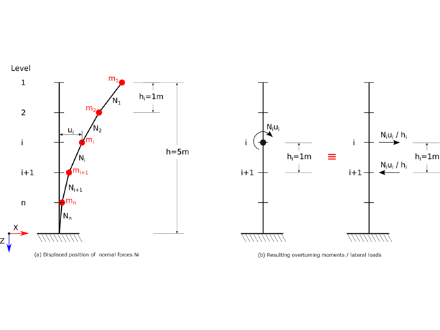
Zgodnie z normami EN 1998-1 sekcje 2.2.2 i 4.4.2.2 do obliczeń stanu granicznego nośności należy przeprowadzić obliczenia z uwzględnieniem teorii drugiego rzędu (efekt P-Δ). Efekt ten nie musi być uwzględniany tylko w przypadku, gdy współczynnik wrażliwości międzykondygnacyjnej jest mniejszy niż 0,1.

Podczas obliczania regularnych konstrukcji wprowadzanie danych często nie jest skomplikowane, ale czasochłonne. Oszczędzaj cenny czas dzięki automatycznemu wprowadzaniu danych. W niniejszym przypadku należy uwzględnić kondygnacje domu jako poszczególne etapy budowy. Dane są wprowadzane przy pomocy programu w języku C#, aby użytkownik nie musiał ręcznie wprowadzać elementów poszczególnych pięter.

Zarówno analiza drgań własnych, jak i analiza spektrum odpowiedzi przeprowadzane są na układzie liniowym. Jeżeli w modelu występują nieliniowości, podlega on linearyzacji, dzięki czemu elementy nieliniowe nie są brane pod uwagę w dalszej analizie. Mogą to być na przykład pręty rozciągane, podpory nieliniowe lub przeguby nieliniowe. W tym artykule pokazano, w jaki sposób można nimi zarządzać w analizie dynamicznej.

Aby ocenić, czy w obliczeniach dynamicznych konieczne jest również uwzględnienie analizy drugiego rzędu, w normie EN 1998‑1, sekcje 2.2.2 i 4.4.2.2 zawarto współczynnik wrażliwości międzykondygnacyjnego znoszenia θ. Można ją obliczyć i przeanalizować za pomocą programów RFEM 6 i RSTAB 9.