13 Wyniki
Wyświetl wyniki:
Sortuj według:

Ocena przemieszczenia kondygnacji w budynku jest kluczowa dla zapewnienia zadowalających parametrów konstrukcyjnych poprzez ograniczenie przemieszczenia kondygnacji. Nadmierne znoszenie może powodować niestateczność systemu i powodować uszkodzenia elementów niekonstrukcyjnych, takich jak ściany działowe. W tym artykule opisano procedurę wyznaczania przemieszczeń międzykondygnacyjnych zgodnie z ASCE 7-22 i rozszerzeniem Model budynku w programie RFEM 6.
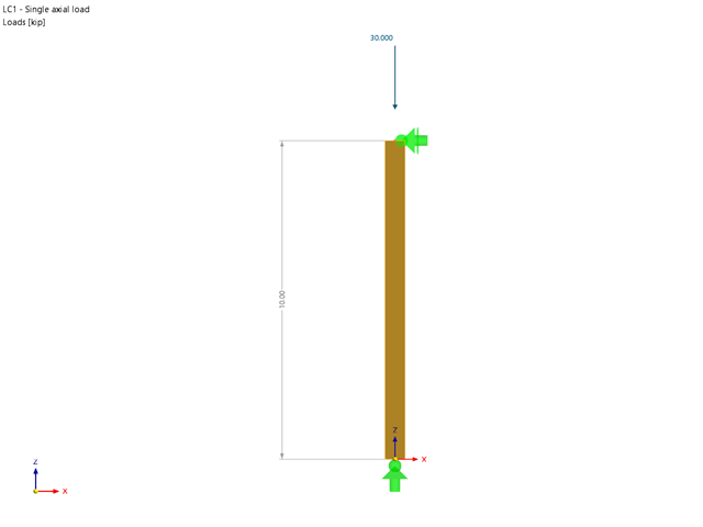
Rozszerzenie Wymiarowanie drewna umożliwia wymiarowanie słupów drewnianych zgodnie ze standardową metodą ASD 2018 NDS. Dokładne wyznaczenie nośności na ściskanie oraz współczynników redukcyjnych dla prętów drewnianych jest konieczne dla bezpieczeństwa konstrukcji. Poniższy artykuł weryfikuje maksymalną wytrzymałość na wyboczenie krytyczną obliczoną w module rozszerzeniowym Wymiarowanie drewna przy użyciu równań analitycznych krok po kroku zgodnie z normą NDS 2018, w tym współczynników dostosowania przy ściskaniu, skorygowanej wartości obliczeniowej na ściskanie i końcowego stopnia wyboczenia.
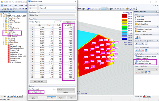
Za pomocą programów RWIND 2 i RFEM 6 można teraz obliczać obciążenia wiatrem na podstawie zmierzonego eksperymentalnie ciśnienia wiatru na powierzchnie. Zasadniczo dostępne są dwie metody interpolacji, umożliwiające rozłożenie ciśnienia mierzonego w izolowanych punktach na powierzchnie. Żądany rozkład ciśnienia można uzyskać za pomocą odpowiedniej metody i ustawień parametrów.
Zgodność z przepisami budowlanymi, takimi jak Eurokod, jest niezbędna dla zapewnienia bezpieczeństwa, integralności konstrukcji i trwałości budynków i konstrukcji. Obliczeniowa mechanika płynów (CFD) odgrywa istotną rolę w tym procesie, symulując zachowanie płynów, optymalizując projekty i pomagając architektom i inżynierom w spełnieniu wymagań Eurokodu związanych z analizą obciążenia wiatrem, wentylacją naturalną, bezpieczeństwem pożarowym i efektywnością energetyczną. Integrując CFD z procesem projektowania, profesjonaliści mogą tworzyć bezpieczniejsze, wydajniejsze i zgodne z przepisami budynki, które spełniają najwyższe standardy konstrukcyjne i projektowe w Europie.
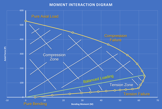
Nowością w programie RFEM 6 podczas wymiarowania słupów betonowych jest możliwość generowania wykresu interakcji momentów zgodnie z ACI 318-19 [1]. Podczas wymiarowania prętów żelbetowych istotnym narzędziem jest wykres interakcji momentów. Wykres interakcji momentów przedstawia zależność między momentem zginającym a siłą osiową w dowolnym punkcie zbrojenia. Cenne informacje, takie jak wytrzymałość i zachowanie betonu w różnych warunkach obciążenia, wyświetlane są wizualnie.
Metoda CSA S16:19 Skutki stateczności w analizie sprężystej w Załączniku O.2 stanowi alternatywę dla metody Uproszczonej analizy stateczności z punktu 8.4.3. W tym artykule zostaną opisane wymagania załącznika O.2 i zastosowania w RFEM 6.
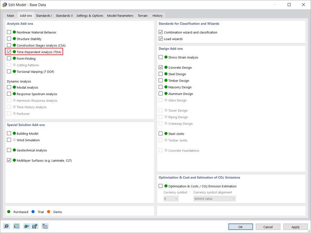
W tym artykule pokazano, w jaki sposób rozszerzenie „Analiza zależna od czasu” jest zintegrowane w programach RFEM 6 i RSTAB 9. Opisuje sposób definiowania danych wejściowych, takich jak charakterystyka materiału zależna od czasu, sposób określania typu analizy i czasy obciążenia.
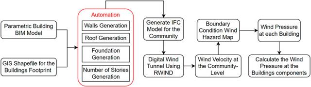
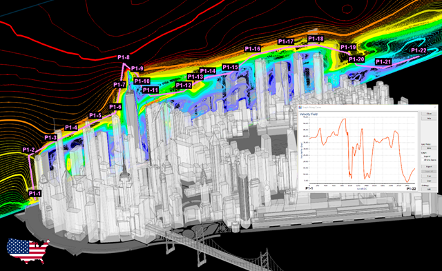
W artykule tym opracowano nowatorskie podejście do generowania modeli CFD na poziomie miejscowości poprzez połączenie modelowania informacji o budynku (BIM) i systemów informacji geograficznej (GIS) w celu zautomatyzowania generowania trójwymiarowego modelu terenu o wysokiej rozdzielczości, który zostanie wykorzystany jako dane wejściowe dla cyfrowego tunelu aerodynamicznego z wykorzystaniem RWIND.
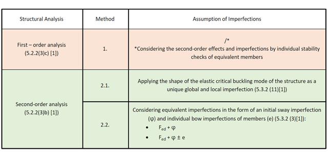
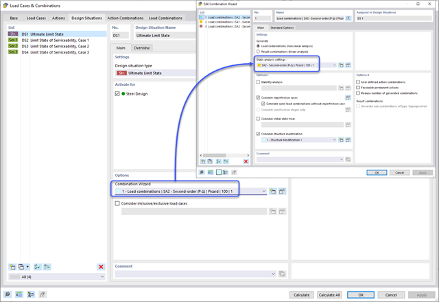
W tym artykule w Bazie informacji omówiono różne metody analizy stateczności opisane w normie EN 1993-1-1:2005 i ich zastosowanie w programie RFEM 6.

W programie RFEM 6 możliwe jest definiowanie spoin liniowych na liniach między powierzchniami i obliczanie naprężeń w spoinie za pomocą rozszerzenia Analiza naprężeniowo-odkształceniowa. Z tego artykułu dowiesz się, jak to zrobić.
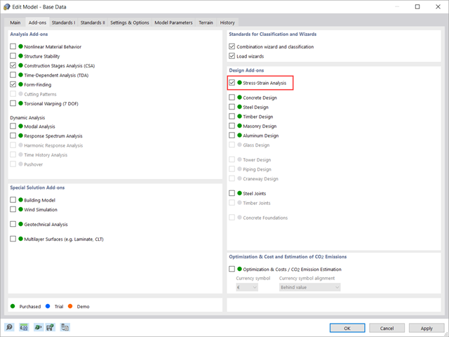
W tym artykule pokazano, jak zarządzać danymi wejściowymi dla konfiguracji obliczeń prętów i powierzchni w rozszerzeniu Analiza naprężeniowo-odkształceniowa.

Zaletą modułu dodatkowego RFEM 6 Steel Joints jest możliwość analizy połączeń stalowych przy użyciu modelu MES, dla którego modelowanie przebiega w pełni automatycznie w tle. Elementy składowe złącza stalowego, które kontrolują modelowanie, można wprowadzić, definiując je ręcznie lub korzystając z dostępnych szablonów w bibliotece. Ta ostatnia metoda została opisana w poprzednim artykule z Bazy wiedzy zatytułowanym „Definiowanie komponentów połączenia stalowego przy użyciu biblioteki”. Definiowanie parametrów do wymiarowania połączeń stalowych jest tematem artykułu w bazie wiedzy „Projektowanie połączeń stalowych w RFEM 6”.

Rozszerzenie Projektowanie konstrukcji aluminiowych dla RFEM 6 wymiaruje pręty aluminiowe ze względu na stan graniczny nośności i użytkowalności zgodnie z Eurokodem 9. Ponadto możliwe jest wymiarowanie zgodnie z ADM 2020 (norma amerykańska).