67 Wyniki
Wyświetl wyniki:
Sortuj według:

- 002876
- Ogólne informacje
- Projektowanie konstrukcji betonowych RFEM 6
- Projektowanie konstrukcji betonowych RSTAB 9
W przypadku obliczeń betonu wyniki zbrojenia można wyświetlić w tabelach osobno w zależności od sytuacji obliczeniowych.

W rozszerzeniu Projektowanie konstrukcji betonowych dla programu RFEM 6 można przeprowadzić obliczenia odporności ogniowej ścian i płyt żelbetowych zgodnie z uproszczoną metodą tabelaryczną (EN 1992-1-2, rozdział 5.4.2 oraz tabele 5.8 i 5.9).

W rozszerzeniu Projektowanie konstrukcji betonowych można zdefiniować istniejące pionowe zbrojenie na ścinanie. Jest to następnie uwzględniane przy obliczaniu wytrzymałości na przebicie.

- 002801
- Ogólne informacje
- Projektowanie konstrukcji betonowych RFEM 6
- Projektowanie konstrukcji betonowych RSTAB 9
Masz indywidualne przekroje słupów i ścian o różnej geometrii, które wymagają obliczenia nośności na przebicie?
Nie ma problemu. W programie RFEM 6 można przeprowadzić obliczenia na przebicie nie tylko dla przekrojów prostokątnych i okrągłych, ale także dla dowolnego kształtu przekroju.

Rozszerzenie Analiza modalna umożliwia automatyczne zwiększanie poszukiwanych wartości własnych do momentu osiągnięcia zdefiniowanego współczynnika efektywnej masy modalnej. Uwzględniane są wszystkie kierunki translacyjne, które zostały aktywowane jako masy do analizy modalnej.
W ten sposób można łatwo obliczyć wymagane 90% efektywnej masy modalnej dla metody spektrum odpowiedzi.

W przypadku analizy spektrum odpowiedzi modeli budynków można wyświetlić współczynniki wrażliwości dla kierunków poziomych według kondygnacji.
Dzięki tym kluczowym wartościom można zinterpretować wrażliwość na efekty stateczności.

- 002691
- Ogólne informacje
- Projektowanie konstrukcji betonowych RFEM 6
- Projektowanie konstrukcji betonowych RSTAB 9
W rozszerzeniu Projektowanie konstrukcji betonowych można przeprowadzić uproszczone obliczenia odporności ogniowej słupów (Rozdział 5.3.2) i belek (Rozdział 5.6), zgodnie z EN 1992-1-2.
W przypadku uproszczonych obliczeń odporności ogniowej dostępne są następujące metody weryfikacji:
- Słupy: Minimalne wymiary przekroju prostokątnego i okrągłego wg tabeli 5.2a oraz równania 5.7 do obliczania czasu ekspozycji pożarowej
- Belki: Minimalne wymiary i odległości między środkami zgodnie z Tabelą 5.5 i Tabelą 5.6
Siły wewnętrzne do obliczeń odporności ogniowej można wyznaczyć przy użyciu dwóch metod.
- 1: W tym przypadku siły wewnętrzne z wyjątkowej sytuacji obliczeniowej są bezpośrednio uwzględniane w obliczeniach.
- 2: Siły wewnętrzne z obliczeń w temperaturze normalnej są redukowane za pomocą współczynnika Eta,fi (ηfi) i są następnie wykorzystywane do obliczeń odporności ogniowej.
Ponadto istnieje możliwość modyfikacji rozstawu osi zgodnie z równ. 5.5.
.png?mw=640&hash=403c565ab80c4dd45c2d1356634fb74a90428b70)
W bibliotece konstrukcji warstwowych dostępni są następujący producenci drewna klejonego krzyżowo:
- Binderholz (USA)
- KLH (USA, CAN)
- Kalesnikoff (USA, CAN)
- Nordic Structures (USA, CAN)
- Mercer Mass Timber
- SmartLam
- Sterling Structural
- Konstrukcje nośne wymienione w Lignatec wydanie 32 "Drewno klejone krzyżowo z produkcji szwajcarskiej"
Wczytanie konstrukcji z biblioteki konstrukcji warstw powoduje automatyczne przejęcie wszystkich istotnych parametrów. Biblioteka jest stale aktualizowana.

Rozszerzenie Projektowanie konstrukcji betonowych umożliwia wymiarowanie prętów i powierzchni ze względu na zmęczenie zgodnie z EN 1992-1-1, rozdział 6.8.
W przypadku obliczeń zmęczenia można opcjonalnie wybrać dwie metody lub poziomy obliczeniowe w konfiguracjach obliczeniowych:
- Poziom obliczeniowy 1: Obliczenia uproszczone wg. do 6.8.6 i 6.8.7(2) Kryterium uproszczone jest stosowane dla częstych kombinacji oddziaływań zgodnie z EN 1992-1-1, rozdział 6.8.6 (2) oraz EN 1990, równ. (6.15b) wraz z obciążeniami od ruchu drogowego w stanie użytkowalności. Dla stali zbrojeniowej sprawdzany jest maksymalny zakres naprężeń zgodnie z 6.8.6. Naprężenie ściskające w betonie jest określane za pomocą górnego i dolnego dopuszczalnego naprężenia zgodnie z 6.8.7(2).
- Poziom analizy 2: Obliczanie równoważnego naprężenia niszczącego zgodnie z 6.8.5 i 6.8.7(1) (uproszczone obliczenia na zmęczenie): Obliczenia z wykorzystaniem zakresów równoważnych naprężeń niszczących są przeprowadzane dla kombinacji zmęczeniowych, zgodnie z EN 1992-1-1, rozdział 6.8.3, równ. (6.69) o specyficznie zdefiniowanym oddziaływaniu cyklicznym Qfat .

W rozszerzeniu Projektowanie konstrukcji betonowych można przeprowadzać obliczenia sejsmiczne dla prętów żelbetowych zgodnie z EC 8. Są to między innymi następujące funkcje:
- Konfiguracje obliczeń sejsmicznych
- Rozróżnianie klas ciągliwości DCL, DCM, DCH
- Możliwość przeniesienia współczynnika odpowiedzi z analizy dynamicznej
- Sprawdzenie wartości granicznej współczynnika odpowiedzi
- Weryfikacja nośności dla "Wytrzymały słup - słaba belka"
- Uszczegółowienie i reguły szczególne dla współczynnika ciągliwości krzywizny
- Uszczegółowienie i reguły szczególne dla ciągliwości lokalnej

Teraz w rozszerzeniu Projektowanie konstrukcji betonowych można wymiarować elementy wykonane z betonu zbrojonego włóknami zgodnie z wytyczną "DAfStb Steel Fiber-Reinforced Concrete".
Ta opcja jest dostępna dla obliczeń zgodnie z EN 1992-1-1. Obliczenia zgodnie z wytyczną DAfStb są przeprowadzane po przypisaniu betonu typu "Fibrobeton" do elementu konstrukcyjnego z betonu zbrojonego.
Przejdź do filmu
W zakładce "Zbrojenie na ścinanie" można wybrać opcję "Powiązania krzyżowe na wolnych prętach zbrojeniowych z aktywnym wyborem w oknie graficznym". Pozwala to na umieszczenie dodatkowych powiązań krzyżowych na wolnych prętach zbrojenia podłużnego.
Pozycję więzów krzyżowych można aktywować lub dezaktywować w infografice. Powiązania krzyżowe są uwzględniane podczas kontroli stanu granicznego nośności i obliczeń konstrukcji. Są one dostępne dla obliczeń zgodnie z EN 1992-1-1.
Przejdź do filmu
W rozszerzeniu Projektowanie konstrukcji betonowych można wymiarować dowolny przekrój RSECTION. Otulinę betonową, zbrojenie na ścinanie i zbrojenie podłużne definiuje się bezpośrednio w RSECTION.
Po zaimportowaniu przekroju ze zbrojeniem RSECTION do programu RFEM 6, można go również wykorzystać do obliczeń w rozszerzeniu Projektowanie konstrukcji betonowych.
Przejdź do filmu
W programie RFEM zaimplementowano bibliotekę płyt z drewna klejonego krzyżowo, z której można importować konstrukcje warstwowe różnych producentów (np. Binderholz, KLH, Piveteaubois, Södra, Züblin Timber, Schilliger, Stora Enso). Oprócz grubości i materiałów warstw podane są również informacje o redukcji sztywności i łączeniu wąskich boków.
Przejdź do filmu
- 002557
- Ogólne informacje
- Projektowanie konstrukcji betonowych RFEM 6
- Projektowanie konstrukcji betonowych RSTAB 9
Skorzystaj i oszczędzaj czas! Ta funkcja umożliwia jednoczesne definiowanie lub edycję zbrojenia dla kilku prętów lub zbiorów prętów.
Przejdź do filmu
Istniejące zbrojenie powierzchniowe można automatycznie zaprojektować tak, aby pokryć wymagane zbrojenie. Można wybrać, czy automatycznie ma być definiowana średnica zbrojenia, czy też rozstaw prętów.
Przejdź do filmu
- 002469
- Ogólne informacje
- Projektowanie konstrukcji betonowych RFEM 6
- Projektowanie konstrukcji betonowych RSTAB 9
Pracujesz z elementami konstrukcyjnymi składającymi się z płyt? W takim przypadku należy przeprowadzić obliczenia na ścinanie z uwzględnieniem wymagań obliczania przebicia, na przykład zgodnie z 6.4, EN 1992-1-1. Oprócz płyt stropowych można w ten sposób wymiarować również płyty fundamentowe.
W konfiguracji stanu granicznego nośności dla wymiarowania betonu można zdefiniować parametry obliczeń przebicia dla wybranych węzłów.

- 002457
- Ogólne informacje
- Projektowanie konstrukcji aluminiowych RFEM 6
- Projektowanie konstrukcji aluminiowych RSTAB 9
Rozszerzenie Projektowanie konstrukcji aluminiowych oferuje dodatkowe opcje. W tym miejscu można również obliczać przekroje ogólne, które nie są wstępnie zdefiniowane w bibliotece przekrojów. Na przykład, utwórz przekrój w programie RSECTION, a następnie zaimportuj go do RFEM/RSTAB. W zależności od zastosowanej normy projektowej dostępne są różne formaty obliczeń. Obejmuje to na przykład równoważną analizę naprężeń.
Ist zudem eine Lizenz für RSECTION und „Effektive Querschnitte“ vorhanden, so können Sie die Nachweise auch unter Berücksichtigung der effektiven Querschnittswerte nach EN 1999-1-1 führen.

- 002458
- Ogólne informacje
- Projektowanie konstrukcji aluminiowych RFEM 6
- Projektowanie konstrukcji aluminiowych RSTAB 9
Wiesz na pewno, że podczas łączenia elementów rozciąganych za pomocą połączeń śrubowych należy wziąć pod uwagę osłabienie przekroju spowodowane otworami na śruby. Programy do analizy statyczno-wytrzymałościowej również mają na to rozwiązanie. W rozszerzeniu Aluminium Design można wprowadzić lokalną redukcję przekroju pręta. Redukcję przekroju należy wprowadzić jako wartość bezwzględną lub jako procent powierzchni całkowitej.
- 002459
- Ogólne informacje
- Projektowanie konstrukcji aluminiowych RFEM 6
- Projektowanie konstrukcji aluminiowych RSTAB 9
Rozszerzenie Skręcanie skrępowane (7 stopni swobody) umożliwia przeprowadzanie obliczeń konstrukcji prętowych w programach RFEM i RSTAB, z uwzględnieniem deplanacji przekrojów. Wszystkie siły wewnętrzne (N, Vu, Vv, Mt, pri, Mt, sec, Mu, Mv, Mω) określone w ten sposób mogą zostać uwzględnione w analizie naprężeń zastępczych dla obliczeń konstrukcji aluminiowych. Uwaga: Ta funkcja nie jest jeszcze dostępna dla norm projektowych ADM 2020.

- 002462
- Ogólne informacje
- Projektowanie konstrukcji aluminiowych RFEM 6
- Projektowanie konstrukcji aluminiowych RSTAB 9
Czy do określenia współczynnika obciążenia krytycznego w ramach analizy stateczności użyto dodatkowego solwera wewnętrznych wartości własnych? W takim przypadku można następnie wyświetlić kształt wzorca projektowanego obiektu.

- 002451
- Ogólne informacje
- Projektowanie konstrukcji aluminiowych RFEM 6
- Projektowanie konstrukcji aluminiowych RSTAB 9
- Obliczanie ugięć i porównanie z normatywnymi lub ręcznie dostosowanymi wartościami granicznymi
- Uwzględnienie wygięcia wstępnego w analizie ugięcia
- W zależności od typu sytuacji obliczeniowej możliwe są różne wartości graniczne
- Ręczne dostosowywanie długości odniesienia i segmentacji według kierunku
- Obliczenia ugięć w odniesieniu do konstrukcji wyjściowej lub konstrukcji odkształconej
- Dalsze szczegółowe weryfikacje w zależności od wybranej normy obliczeniowej (np. weryfikacja drgań zgodnie z EN 1999-1-1, 7.2.3)
- Graficzne wyświetlanie wyników zintegrowane w programie RFEM/RSTAB, na przykład stopień wykorzystania wartości granicznej, odkształcenie lub ugięcie
- Pełna integracja wyników z raportem RFEM/RSTAB

- 002452
- Ogólne informacje
- Projektowanie konstrukcji aluminiowych RFEM 6
- Projektowanie konstrukcji aluminiowych RSTAB 9
Program wykonuje za Ciebie dużo pracy. Na przykład kombinacje obciążeń lub wyników, które są niezbędne dla stanu granicznego użytkowalności, są generowane i obliczane w programie RFEM/RSTAB. Te sytuacje obliczeniowe można wybrać w rozszerzeniu Aluminium Design w celu przeprowadzenia analizy ugięcia. W zależności od wprowadzonej przechyłki i wybranego układu odniesienia program określa obliczone wartości deformacji w każdym punkcie pręta. Następnie są one porównywane z wartościami granicznymi.
W konfiguracji Stan graniczny użytkowalności można ustawić wartość graniczną, która ma być obserwowana dla odkształcenia dla każdego komponentu z osobna. Jako dopuszczalną wartość graniczną definiuje się maksymalne odkształcenie w zależności od długości odniesienia. Definiując podpory obliczeniowe, można segmentować komponenty. W ten sposób można automatycznie określić odpowiednią długość odniesienia dla każdego kierunku obliczeń.
To nie wszystko. W oparciu o położenie przypisanych podpór obliczeniowych program automatycznie umożliwia rozróżnienie belek i belek wspornikowych. W ten sposób określana jest odpowiednio wartość graniczna.

- 002453
- Ogólne informacje
- Projektowanie konstrukcji aluminiowych RFEM 6
- Projektowanie konstrukcji aluminiowych RSTAB 9
Obliczenia w stanie granicznym użytkowalności można znaleźć w tabelach wyników w rozszerzeniu do obliczeń dla aluminium. Są tam już w pełni zintegrowane. Istnieje możliwość uzyskania wyników obliczeń w każdym punkcie wymiarowanych prętów ze wszystkimi szczegółami. Można również użyć grafiki z wynikami współczynników obliczeniowych.
W razie potrzeby wszystkie tabele wyników i grafiki można uwzględnić jako część wyników obliczeń aluminium w globalnym raporcie wydruku programu RFEM/RSTAB. Program RFEM/RSTAB umożliwia również wyświetlanie i dokumentowanie wartości deformacji całej konstrukcji niezależnie od tego, czy jest to moduł dodatkowy.

- 002454
- Ogólne informacje
- Projektowanie konstrukcji aluminiowych RFEM 6
- Projektowanie konstrukcji aluminiowych RSTAB 9
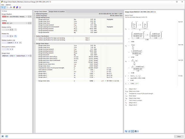
Czy bardzo to lubisz? My też! Z tego powodu wszystkie sprawdzenia dotyczące normy projektowej są wyświetlane w przejrzysty sposób. Dla każdej kontroli obliczeń należy zdefiniować kryterium wykorzystania. Szczegóły obliczeń, w których wartości wejściowe, wyniki pośrednie i wyniki końcowe są uporządkowane w sposób uporządkowany, są dostępne dla każdej kontroli obliczeń. Proces obliczeń wraz ze wszystkimi wzorami, normami i wynikami znajduje się w oknie informacyjnym, w którym wyświetlane są szczegóły obliczeń.
- 002455
- Ogólne informacje
- Projektowanie konstrukcji aluminiowych RFEM 6
- Projektowanie konstrukcji aluminiowych RSTAB 9
Weryfikacje można znaleźć w rozszerzeniu dotyczącym konstrukcji aluminiowych w postaci przejrzystych tabel. Można również przedstawić graficznie rozwój współczynników obliczeniowych. Rozbudowane opcje filtrowania są dostępne zarówno w tabeli, jak i w danych wyjściowych graficznych. W ten sposób program może wyświetlać żądane obliczenia według stanu granicznego lub typu obliczeniowego.
- 002456
- Ogólne informacje
- Projektowanie konstrukcji aluminiowych RFEM 6
- Projektowanie konstrukcji aluminiowych RSTAB 9
Przy obliczaniu granicznego ugięcia należy wziąć pod uwagę określone długości odniesienia. Te długości odniesienia i sprawdzane segmenty można definiować niezależnie od siebie, w zależności od kierunku. W tym celu należy zdefiniować podpory obliczeniowe w węzłach pośrednich pręta i przypisać je do odpowiedniego kierunku dla analizy deformacji. Tworzy to segmenty, w których można uwzględnić przechyłkę dla każdego kierunku i segmentu.

- 002460
- Ogólne informacje
- Projektowanie konstrukcji aluminiowych RFEM 6
- Projektowanie konstrukcji aluminiowych RSTAB 9
Należy upewnić się, że zdefiniowanie długości efektywnych w aluminiowym module dodatkowym jest warunkiem niezbędnym do przeprowadzenia analizy stateczności. W tym celu w oknie dialogowym należy zdefiniować podpory węzłowe i współczynniki długości efektywnej. Czy chcesz przejrzyście udokumentować podpory węzłowe i wynikające z nich segmenty wraz z powiązanym współczynnikiem długości efektywnej? W celu sprawdzenia wprowadzonych danych najlepiej jest użyć prezentacji graficznej w oknie roboczym programu RFEM/RSTAB. Oznacza to, że możesz zrozumieć projekt w dowolnym momencie i bez większego wysiłku.
- 002463
- Ogólne informacje
- Projektowanie konstrukcji aluminiowych RFEM 6
- Projektowanie konstrukcji aluminiowych RSTAB 9
W przypadku obliczeń zgodnie z Eurokodem 9, można znaleźć parametry zintegrowanych załączników krajowych dla następujących krajów:
-
 DIN EN 1999-1-1/NA:2021-03 (Niemcy)
 -
 ÖNORM EN 1999-1-1/NA:2017-11 (Austria)
 -
 SN EN 1999-1-1/NA:2015-01 (Szwajcaria)
 -
 BDS EN 1999-1-1/NA:2014-05 (Bułgaria)
 -
 BS EN 1999-1-1/NA:2014-03 (Wielka Brytania)
 -
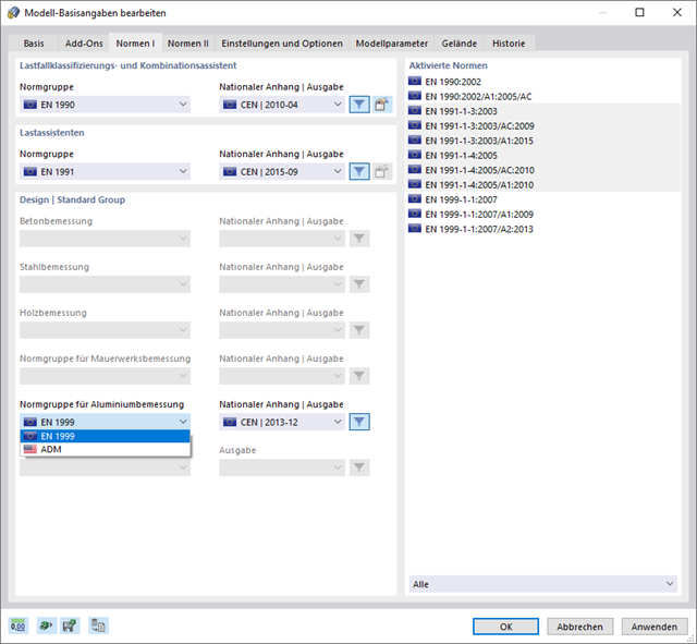
 CEN 1999-1-1/2013-12 (Unia Europejska)
 -
 CYS EN 1999-1-1/NA:2019-08 (Cypr)
 -
 CZE EN 1999-1-1/NA:2015-09 (Republika Czeska)
 -
 DS EN 1999-1-1/NA:2019-09 (Dania)
 -
 ELOT EN 1999-1-1/NA:2013-12 (Grecja)
 -
 EVS EN 1999-1-1/NA:2014-01 (Estonia)
 -
 HRN EN 1999-1-1/NA:2015-02 (Chorwacja)
 -
 I S. EN 1999-1-1/NA:2015-01 (Irlandia)
 -
 ILNAS EN 1999-1-1/NA:2013-12 (Luksemburg)
 -
 IST EN 1999-1-1/NA:2014-03 (Islandia)
 -
 LST EN 1999-1-1/NA:2014-03 (Litwa)
 -
 LVS EN 1999-1-1/NA:2015-01 (Łotwa)
 -
 MSZ EN 1999-1-1/NA:2014-04 (Węgry)
 -
 NBN EN 1999-1-1/NA:2014-01 (Belgia)
 -
 NEN EN 1999-1-1/NA:2014-01 (Holandia)
 -
 NF EN 1999-1-1/NA:2016-07 (Francja)
 -
 NP EN 1999-1-1/NA:2014-11 (Portugalia)
 -
 NS EN 1999-1-1/NA:2014-04 (Norwegia)
 -
 PN EN 1999-1-1/NA:2014-05 (Polska)
 -
 SFS EN 1999-1-1/NA:2018-01 (Finlandia)
 -
 SIST EN 1999-1-1/NA:2014-05 (Słowenia)
 -
 SR EN 1999-1-1/NA:2015-01 (Rumunia)
 -
 SS EN 1999-1-1/NA:2013-12 (Szwecja)
 -
 STN EN 1999-1-1/NA:2014-05 (Słowacja)
 -
 TKP EN 1999-1-1/NA:2010-01 (Białoruś)
 -
 UNE EN 1999-1-1/NA:2014-01 (Hiszpania)
 -
 UNI EN 1999-1-1/NA:2014-02 (Włochy)

- 002464
- Wyniki
- Projektowanie konstrukcji aluminiowych RFEM 6
- Projektowanie konstrukcji aluminiowych RSTAB 9
Jak zwykle, wprowadzasz układ i obliczasz siły wewnętrzne w programach RFEM i RSTAB. Masz nieograniczony dostęp do obszernych bibliotek materiałów i przekrojów. Czy wiesz, że za pomocą programu RSECTION można tworzyć przekroje ogólne? Oszczędza to dużo pracy.
Nie bój się'dodatkowych okien i chaosu przy wprowadzaniu danych! Dzieje się tak, ponieważ wymiarowanie aluminium jest w pełni zintegrowane z programami głównymi i automatycznie uwzględnia konstrukcję oraz istniejące wyniki obliczeń. Dalsze dane wejściowe dla obliczeń aluminium, takie jak długości efektywne, redukcje przekroju lub parametry obliczeniowe, można przypisać bezpośrednio do projektowanych obiektów. W wielu miejscach programu najlepiej jest użyć funkcji [Wskaż] do wyboru grafiki - w prosty i efektywny sposób.