


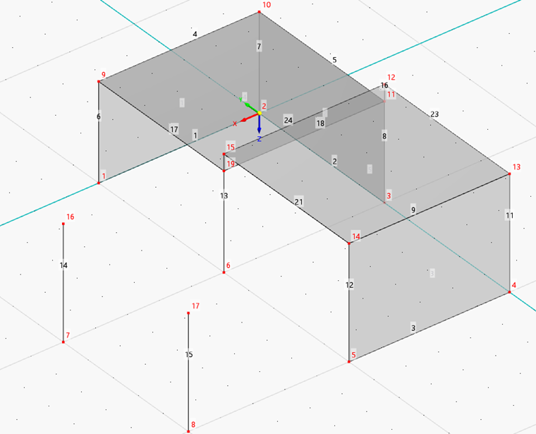
Walls
Three surfaces were created when copying the lines upwards. To check their properties, select all surfaces by drawing a window over the entire model. Then double-click one of the selected wall surfaces.
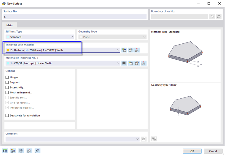
In the 'Stiffness Type' area, 'Without Thickness' has been allocated. Open the list and select the Standard stiffness type (1).
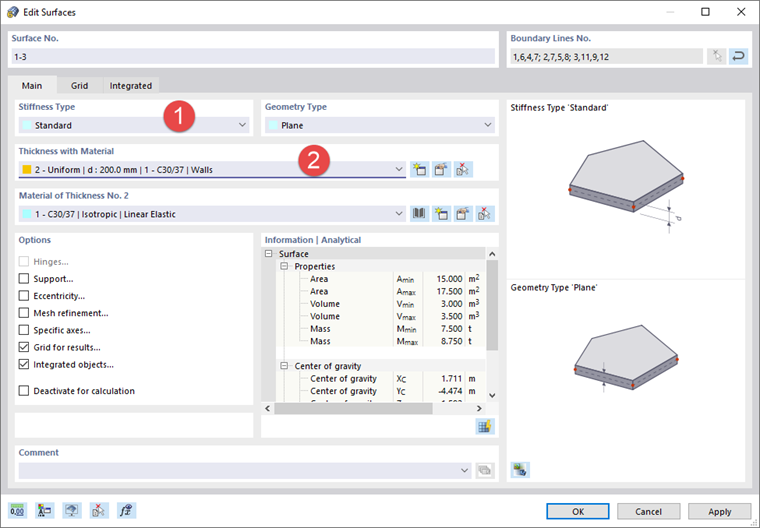
In the 'Thickness with Material' area, select thickness no. 2 that was defined for walls (2).
Click OK. When you click in the empty workspace to cancel the selection, the color of the surfaces changes from red to concrete grey.
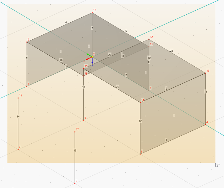
Slabs
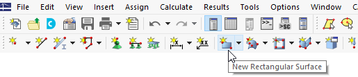
To add the slabs, click the
![]() button on the toolbar.
button on the toolbar.
The 'New Rectangular Surface' dialog box opens.
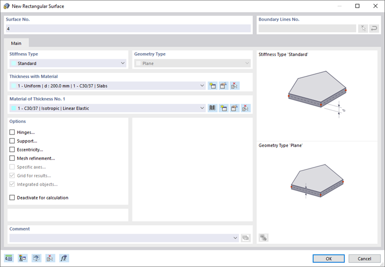
Make sure that the Standard stiffness type and material no. 1 for slabs are set. Then click OK to start defining the surface graphically.
Define the lower slab by clicking its diagonal corners – for example node 9 and then node 11. (It is not required to adjust the work plane because the nodes of the slab already exist.)
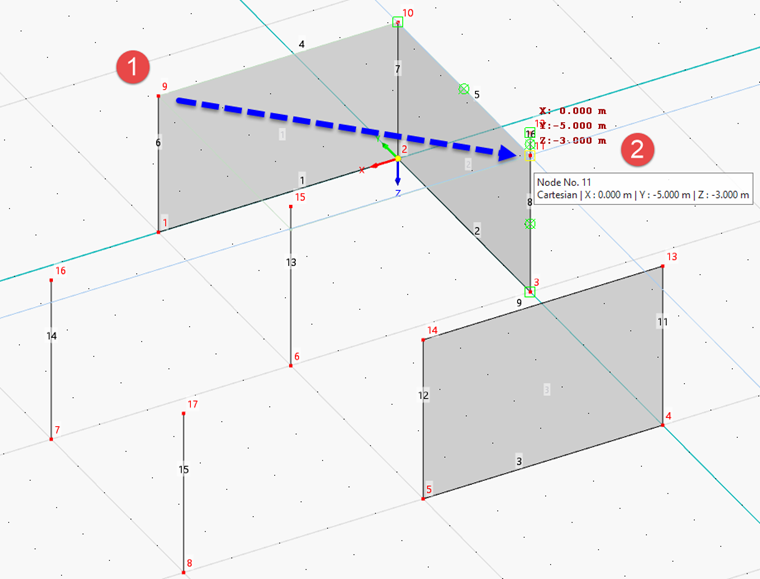
As the stiffness type and thickness also apply to the second slab, continue setting surfaces. Click nodes 15 and 13, for example, to define the higher slab.
Right-click to quit the 'New Rectangular Surface' function.
Connecting Surface
To create the vertical surface between the slabs without any difficulty, the overlapping lines 8 and 10 as well as line 13 must be remodeled.
Dividing lines
Click the
![]() button on the toolbar so that the 'Connect Lines' function is activated. Then draw a window over the entire model.
button on the toolbar so that the 'Connect Lines' function is activated. Then draw a window over the entire model.
The overlapping lines are replaced by continuous lines. Line 13 is split in two lines.
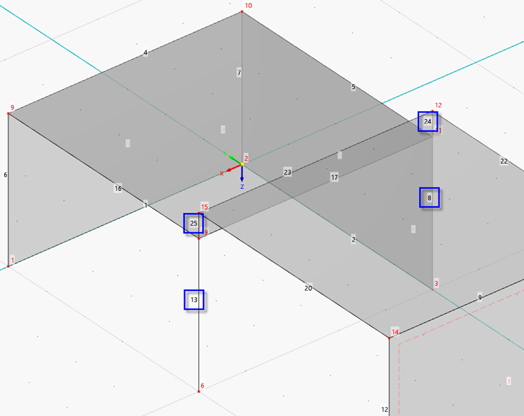
The numbering may again be slightly different to that shown in the image above. Right-click in an empty area of the workspace or press Esc to quit the function.
Defining surface by boundary lines
It would be possible to create the connecting surface by defining a rectangle again. Alternatively, this surface can be created by selecting its boundary lines.
Click
![]() next to the 'New Rectangular Surface' button to open the list of surface shapes.
next to the 'New Rectangular Surface' button to open the list of surface shapes.
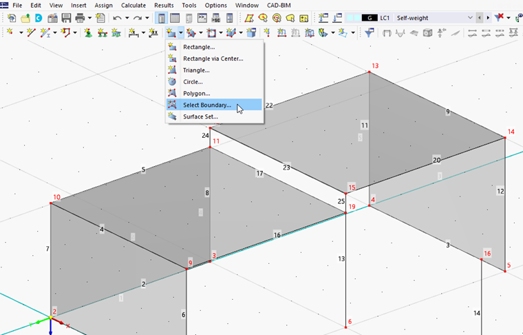
In the 'Thickness with Material' area, select thickness no. 2 that was defined for walls.
Click OK. Then select the lines 17 and 23 through 25 to define the surface between the slabs.
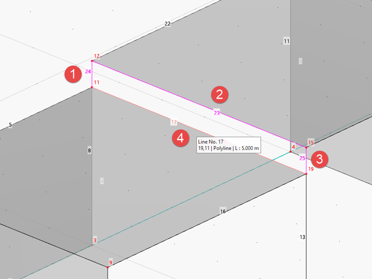
When you have selected the last of the four boundary lines, surface no. 6 is created. Right-click to quit the 'Select Boundary' function.