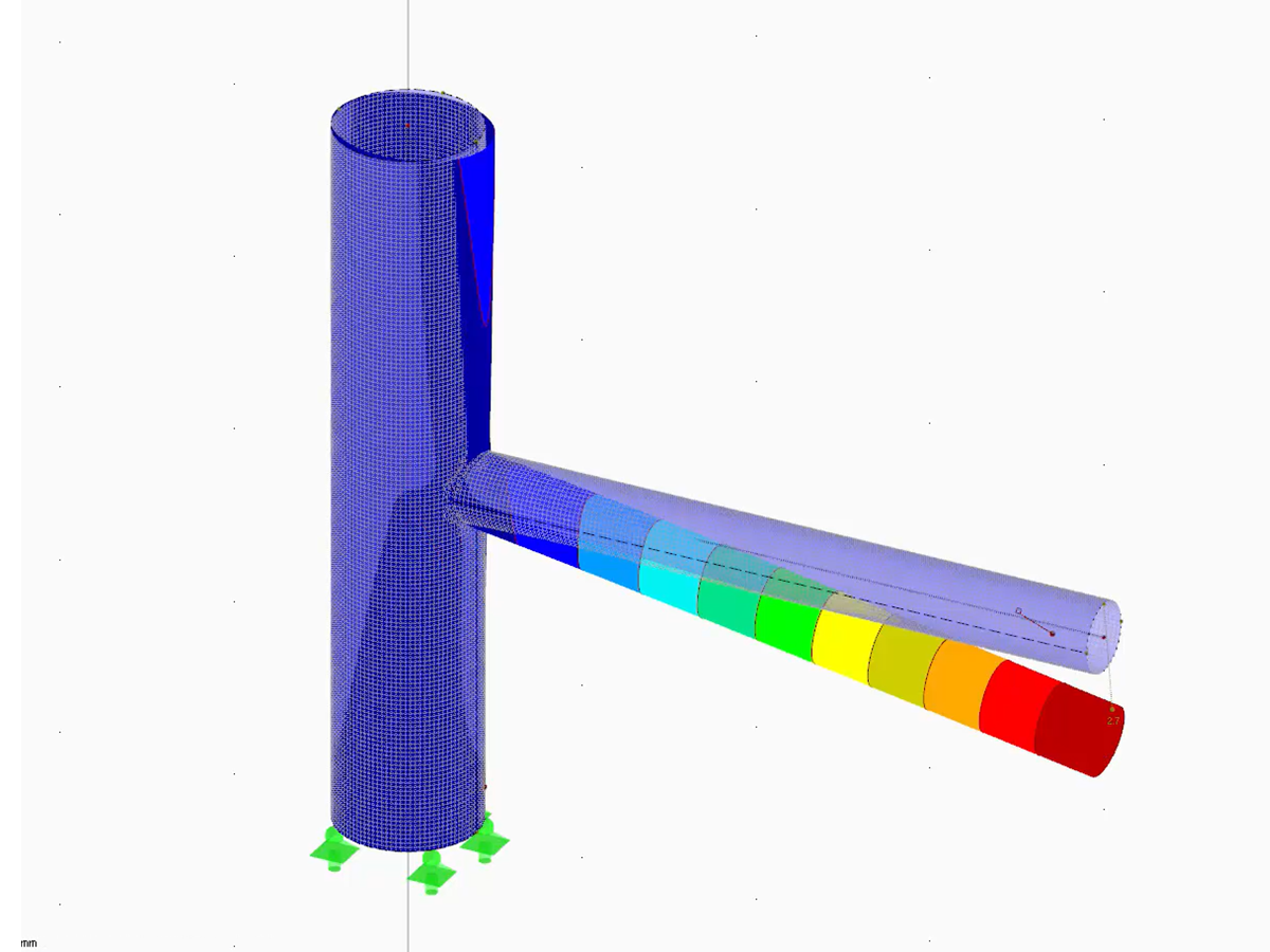
The model enables the automatic generation of pipe cross-sections as a surface model, which is particularly useful in industrial plant engineering and in the detailed analysis of structural pipelines. The RFEM feature generates precise pipe cross-sections along a defined line, optimally visualizing geometric properties and material behavior. The display shows clear, detailed images of the cross-section shape, which considerably facilitates modeling and analysis of pipeline systems. General conditions and modeling tools support the entire design process.
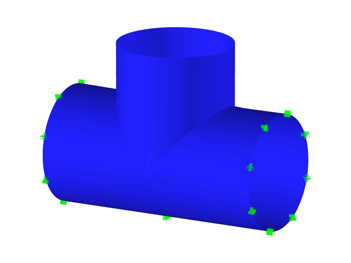
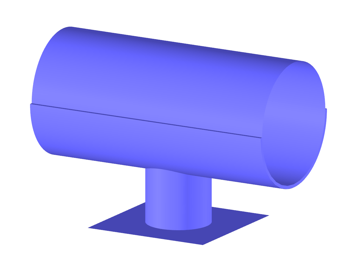
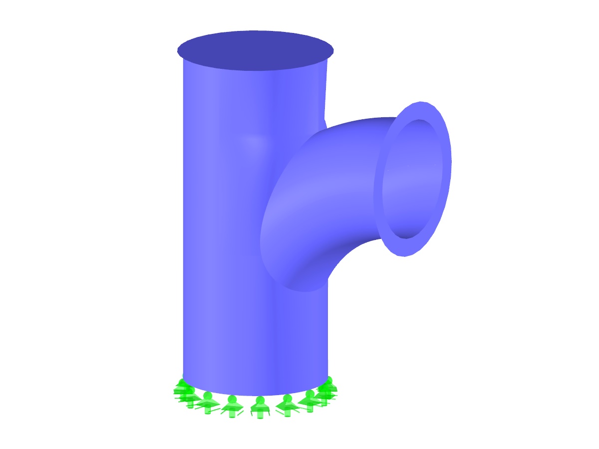
Modeling Surface of Pipe Cross-section
| Number of Nodes | 12 |
| Number of Lines | 4 |
| Number of Surfaces | 1 |
| Number of Load Cases | 1 |
| Total Weight | 0.732 t |
| Dimensions (Metric) | 3.282 x 2.178 x 1.546 m |
| Dimensions (Imperial) | 10.77 x 7.15 x 5.07 feet |
| Program Version | 5.25.01 |
You can download this structural model to use it for training purposes or for your projects. However, we do not assume any guarantee or liability for the accuracy or completeness of the model.