


Dlubal customer Voss & Kamb was responsible for the structural analysis and the connections.
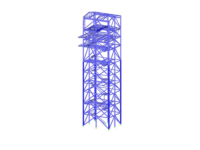
Boiler Supporting Structure and Boiler Roof
The load capacity of the boiler supporting structure with a height of 124 m (406.8 ft) amounts to about 8,400 t (9,259 US tons). Due to the high loading, the structure is made completely of box sections. At the floor level, the support sections have dimensions of 2.4 m x 2.4 m (7.9 x 7.9 ft) and a wall thickness of 80 mm (3.1 in).
All platforms are fastened to the boiler supporting structure. Half of the platforms (at a height of about 70-122 m / 229.66-400.26 ft) hang in the final state as "hanging houses" on the brackets of the boiler support.
At the rear wall, the flue gas duct (d ~ 15 m / 49 ft) is also suspended on the brackets of the boiler supporting structure.
Due to its location, the structure has to withstand very high wind loads. The analysis and design of the boiler supporting structure (including buckling analysis) were performed with RSTAB.
The boiler roof, with a load capacity of about 900 t (992 US tons), was analyzed and designed with RFEM. The model consists of a combination of members and surfaces (7.5 m / 24.6 ft high beams of the boiler roof). Eurocode 3 was used as the design standard.
Connections in Tekla Structures
The model created in Tekla was imported to RSTAB using the direct interface. The structure was further modified during the analysis.
The detailing of the connections was again performed in Tekla Structures according to the structural analysis.
| Structural Engineering | Structural Analysis and Design Voss & Kamb und Partner GmbH, Kaiserslautern, Germany www.voka-kl.com |
| Contractor | Alstom Boiler Deutschland GmbH, Stuttgart, Germany www.alstom.com |


