Question:
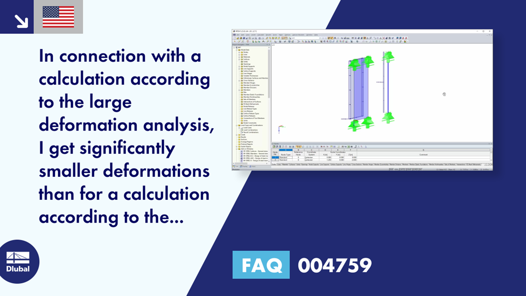
In connection with a calculation according to the large deformation analysis, I get significantly smaller deformations than for a calculation according to the linear static or second-order analysis. How is this possible?
Answer:
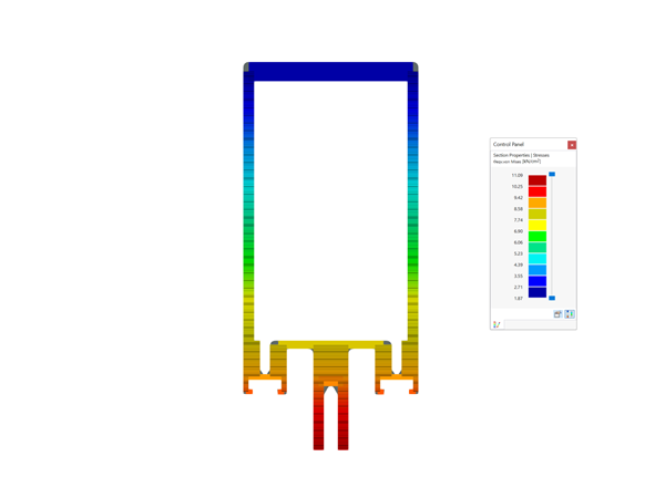
In the calculation according to the large deformation analysis, the membrane stiffness or axial stiffness is also considered with regard to pure bending stress. For the linear static analysis and the second-order analysis, the bending stiffness is only taken into account for the pure bending stress.


.png?mw=350&hash=b2324c4db119938012b5490afaa56e9aa826cdcc)


.png?mw=600&hash=49b6a289915d28aa461360f7308b092631b1446e)