


The Building Model add-on is a special solution add-on, not a design add-on. Consequently, there is no overview in a result table as in the case of the Steel Design add-on, for example.
This chapter introduces the basic functions of the calculation and the results of the add-on.
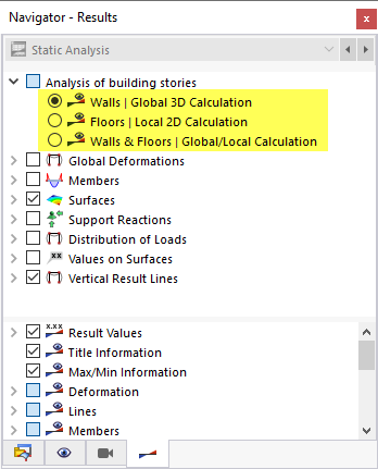
The Building Model add-on divides a building into walls and ceilings. Depending on the Story Modeling, you can select from three analysis types for building stories after the calculation:
- Walls | Global 3D Calculation
- Floors | Local 2D Calculation
- Walls & Floors | Global/Local Calculation
In the Navigator – Results, you can define which results are displayed graphically in the Analysis of building stories category.
The different consideration of the stiffnesses, depending on the selected story modeling, is shown in the following scheme.
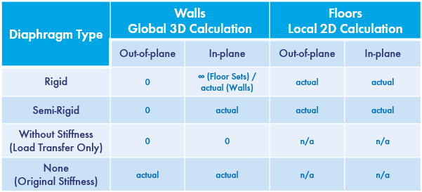
The Walls | Global 3D Calculation analysis type reduces the results to the stiffening elements of the calculation. Surfaces are thus only loaded out of plane. A floor subjected to bending loads does not receive any bending moments in this type of analysis. This applies to semi‑rigid and rigid diaphragms. However, vertical support members–that is, walls and columns–are applied with all stiffnesses. Due to the very high stiffness of the rigid couplings when modeling the floors using rigid diaphragm, no internal forces are displayed in the floor for the "Walls" analysis type. For story modeling using semi-rigid diaphragm, the in-plane stiffnesses are only applied.
For the Floors | Local 2D Calculation analysis type, only the floor sets in the plane are loaded. There are no in-plane stiffnesses. Therefore, in case of a purely horizontal load (for example, due to wind), no internal forces are displayed for this analysis type. The loads are transferred directly to the next floor via the load transfer (hence the name "Local 2D Calculation"). This type of analysis can be compared very well with classic positional analysis – but without complex recalculation as soon as the structure is changed.

The spatial system of a building is resolved in a similar way to a classic position analysis and transferred to a 2D structural system. The load transfer between the individual floor sets becomes apparent when using the "Loads from Distribution Surface" function. The surface load of 2 kN/m² in the image above is divided into 18 kN/m per line in the floor sets via the load transfer surface. In the local 2D calculation, the 18 kN/m are transferred from one floor set to another. The following image shows this graphically.

The function of the load transfer surfaces is described in the chapter Surfaces of the RFEM manual.
The load transfer between the individual floor sets is controlled by modeling the nodal and line supports. The influence is shown in an example in the chapter Story Modeling. Basic information about the support modeling can be found in the chapter Building Stories.
The Walls & Floors | Global/Local Calculation analysis type represents a combination of the global and local calculation. The load transfer between the individual floors is done via the load transfer surfaces! The deformations and internal forces of the floors result from the local 2D calculation. In addition, there are the deformations and internal forces from the global 3D calculation.