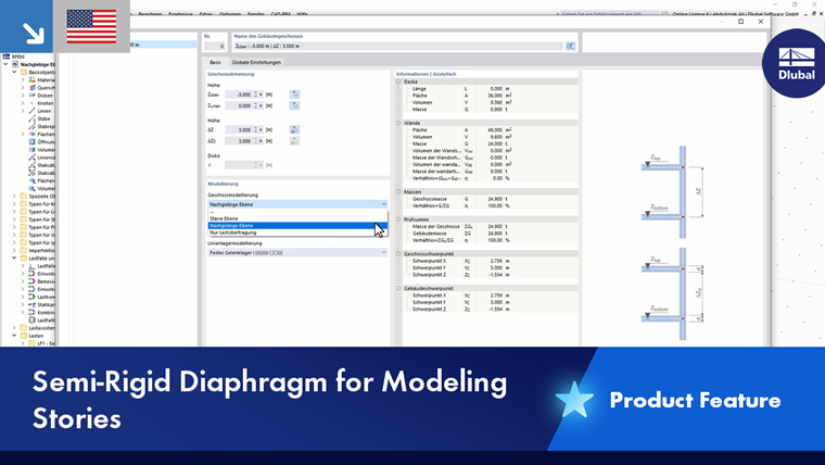
When the Building Model is activated, the Navigator displays data on building stories, slabs, walls, and deep beams.
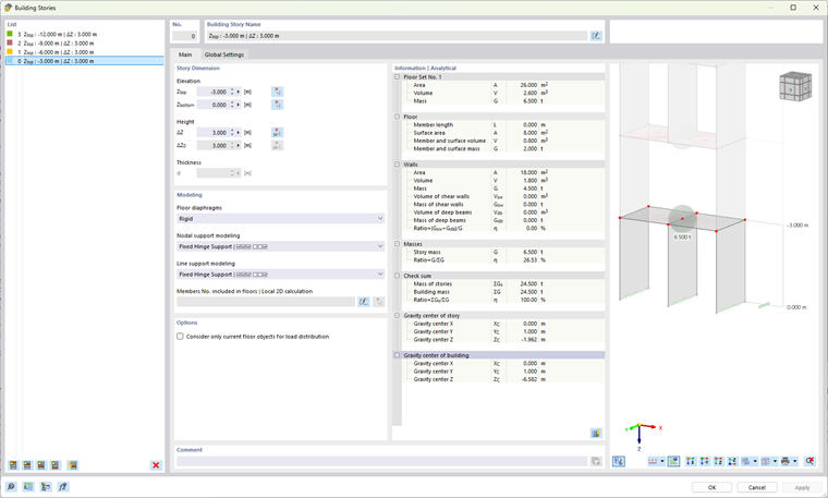
The "Building Stories" dialog box consists of two tabs.
Main
In the Main tab, you can define the story heights and boundary conditions for the modeling. A "Story" includes all model objects in a certain height section; that is, slabs, walls, and columns.
List
The individual building stories are listed on the left. As is usual in RFEM, the information in the remaining dialog sections refers to the entry you have selected in this list.
You can create new stories by using the buttons below the list. The buttons have the following functions:
| Button | Designation | Effect |
|---|---|---|

|
New Highest Story | Create a new top story at the top of the list |

|
New Higher Story | Create a new story above the current story |

|
New Lower Story | Create a new story under the current story |

|
New Bottom Story | Create a new bottom story at the bottom of the list |

|
Story Generator | Create stories based on the existing model geometry |

|
Delete Story | Delete the story or stories selected in the list |
Story Dimension
Specify the story height using the "elevation" of the coordinates Ztop and Zbottom. You can also define the story height graphically using the
 button by selecting two nodes in the model.
The "Height" of the coordinates ΔZ describes the story height in relation to the story below. The values are linked to the specifications of the absolute coordinates. The height ΔZ0 represents the clear height between the stories. This value is only relevant if you specify a floor thickness; otherwise, the height difference refers to the central axes of the floors.
The input field for the “Thickness” d is accessible if you define the story height in the “Global settings” tab using the Clear height option. Here, you can specify the floor thickness of the top story surface, which is then taken into account for the clear height ΔZ0.
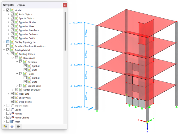
In the Navigator – Display of RFEM, you can define whether and how the story dimensions are displayed in the model.
Modeling
Additional specifications are possible for each story, which you can adjust in this section.
Once the stories have been defined, you can model the building in a “flight mode”. Walls, slabs, and columns can be created very easily and conveniently in the 2D top view. This applies to all selected stories.
Story Modeling
The top floor plane of a story can be modeled in four ways.
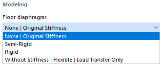
- None | Original stiffness: Using the default setting, the model is analyzed in a global 3D calculation. There are no partial calculations with local 2D analyses for ceilings and walls. However, specific result tables are created for dynamic analysis.
- Semi-Rigid: This approach corresponds to the rigid plane concept, but the FE nodes are not rigidly coupled to the center of gravity. This allows the semi-rigidity of a slab to be taken into account.
- Rigid: At each FE node of the plane, rigid links are applied to the center of gravity of the story, thus coupling the horizontal displacements.
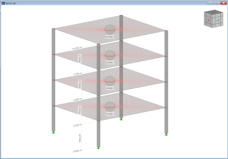
- Without Stiffness | Flexible | Load Transfer Only: The floor slab has no influence on the stiffness in and out of the plane. This element type only "collects" the loads on the floor and transfers them to the supporting elements of the 3D model. It allows you to represent secondary components, such as gratings and load distribution elements, on the 3D model without any further effects.
Depending on the story modeling, the stiffnesses of the slabs and walls are taken into account differently. The following table shows a schematic comparison of the options.
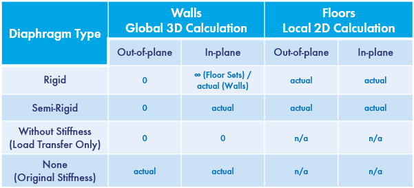
This table is described in more detail in the chapter Overview.
Nodal Support Modeling / Line Support Modeling
In the case of a rigid or semi-rigid diaphragm, you can affect the support of floors for the local 2D model. There are various options available in the lists.
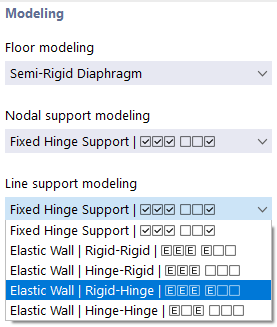
In the case of a "Fixed-Hinge Support", a support is applied in all directions; rotation about the vertical axis is also not possible. You can use the other options to assign an elastic support to both the nodes and the lines of a story. The parameters correspond to the options described in the chapters Nodal Supports and Line Supports of the RFEM manual for determining the stiffness using a fictitious column or fictitious wall. The program determines the spring properties automatically from the boundary conditions consisting of materials, cross-sections, thicknesses, and geometry.
Information | Analytical & Mesh
In this section, you can find specific information about the current story (selected in the "List"). The first column of values lists the analytical information about the story, the second column lists the information calculated on the basis of the generated FE mesh.
Graphic
The right area of the dialog box displays either a static drawing of the story height or a dynamic image of the current story in 3D. You can use the
 button to switch between the two display options. In the 3D view, the usual RFEM options for controlling the graphic are available.
The calculation of Members No. | Local 2D Calculation included in the stories describes one way to transfer horizontal members—for example, ribs or downstand beams—from the wall calculation to the local calculation of the slabs.
For downstand beams, which are typically intended to support the slabs, this is the desired effect.
Global Settings
In the Global Settings tab, you enter the basic specifications for the story modeling that also affect the Main tab.
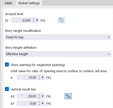
Ground Floor
Define the coordinate Z0 of the lowest point on the ground floor. Use the
 button to graphically select a node of this plane in the work window.
Story Height Modification
There are three options in the list that you can use to control the story height for changes.
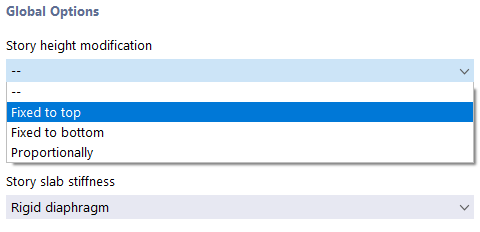
- --: The modifications to the story height do not affect the RFEM model.
- Fixed to top: When changing the height, all other nodes keep their absolute position in relation to the top plane.
- Fixed to bottom: When changing the height, all other nodes keep their absolute position in relation to the bottom plane.
- Proportionally: When changing the height, all other nodes keep their relative position on the modified story with regard to the top and bottom heights.
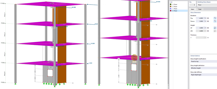
The options for modifying the story height only affect the inner nodes of the respective story. For example, if you increase the story height from 3 m to 4 m (see the following image), the "Fixed to top" option allows an inner node of a divided member or an opening to keep the distance to the top of the story. The distance to the bottom plane of the story increases by 1 m.
Story Height Definition
The list offers two options:
- Effective height: The story height refers to the central axes of the slab surfaces.
- Clear height: You can define the thickness of the upper slab surface in the "Main" tab. This option is also useful for reading the net height (clear height ΔZ0) of a story.
Show Warning for Neglected Openings
For openings in shear walls, you can use the check box to control whether the opening areas should be neglected in the building model calculation. The limit value Δ represents the maximum ratio of the opening area to a surface or a surface cell size. If this value is exceeded, a corresponding warning appears.
You can find further information on modeling openings in the chapter Recommendations.
Vertical Result Line
When activating this check box, RFEM creates a vertical section for the result diagrams. After the calculation, you can read off the values in the individual stories from this vertical result line.
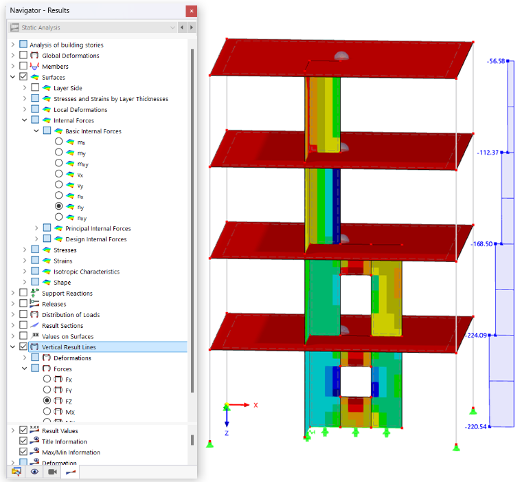
The position of the result line is defined by the distances ΔX and ΔY. The percentage refers to the center of gravity and the directions of the global positive axes.
You can use the
 button to change the input mode and specify the distances in absolute values. They refer to the origin of the axis system.