


A deep beam is a component in reinforced concrete or timber structures that has a large cross-section depth with a short span. According to EN 1992-1-1, Section 5.3.1 (3), for example, a beam is considered to be a deep beam if the span length is less than three times the cross-section depth. ACI 318 Section 9.9 classifies a beam as a deep beam when either the clear span does not exceed four times the overall depth (lₙ ≤ 4h) or the shear span is less than twice the overall member depth (a < 2h). CSA A23.3 classifies deeps beams through Clause 11.4, including a clear span ≤ 4 × overall depth (lₙ ≤ 4h) or a concentrated load located within twice the member depth from the support face (a ≤ 2d). Examples of deep beams are window and door lintels, downstand beams, or split-level slabs. For each deep beam, RFEM creates a result beam that converts the surface internal forces into member internal forces by integration, and allows for design as a member.
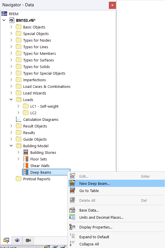
To define a deep beam, right-click the Deep Beams entry in the 'Building Model' category. Then, select the New Deep Beam option in the shortcut menu.
In the 'Deep Beams' dialog box, you can then define the properties of the structural components.

Assignable objects
In most cases, a deep beam is described by surfaces and surface cells. If you want to define it via members, select the corresponding option in the list (see the image above).
Surfaces and Surface Cells / Members
Select the surfaces and surface cells or members graphically on the model using the
 button. The numbers of the objects cannot be entered manually.
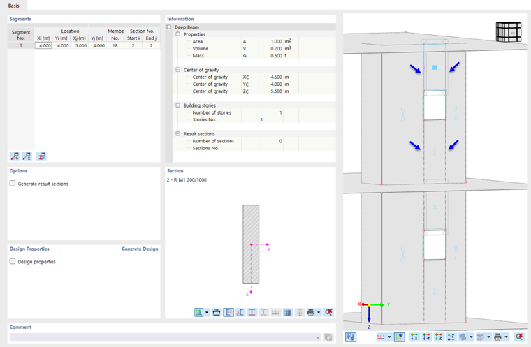
Segments
As a rule, only one segment with a result beam is generated for each surface or surface cell, integrating the internal forces of the surfaces, surface cells, or members. Contiguous objects, such as shear walls, are the exception.
Information / Options / Section
The other sections in this dialog box correspond to those of the Shear Walls dialog.
Design Properties
The internal forces of the result beam can be checked via member design in some design add-ons, for example, in the course of concrete design. To do this, select the Design properties check box in the corresponding section.
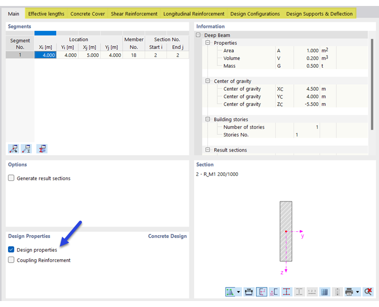
This adds several tabs to the dialog box, where you can specify the conditions for the design.
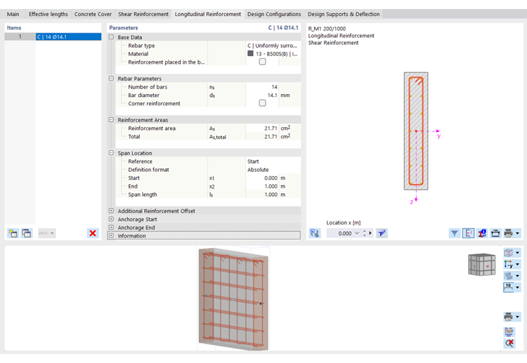
If you select the 'Coupling Reinforcement' check box in the Main tab, another tab is added. There, you can specify the parameters of the diagonal reinforcement for seismic actions, as stipulated in EN 1998-1 Section 5.5.3.5, ACI 318 Section 18.10.7, and CSA A23.3 Section 21.6.8, for example.

In the ultimate configurations of the concrete design, it is possible to apply special construction rules for the vertical and horizontal reinforcement of deep beams.
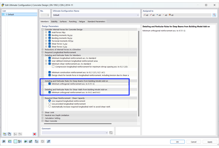
The minimum reinforcement for the orthogonal mesh reinforcement of deep beams is specified in EN 1992-1-1, Section 9.7, ACI 318, Section 9.9.3/9.9.4, and CSA A23.3, Section 11.4, for example.