The add-on automatically detects whether there are the story walls from the highest to the lowest point of the story in a continuous form. In this case, a horizontal result section named "Shear Wall" is generated. Vertical sections are created for discontinuous walls. They are named "Deep Beams." Results are displayed for all generated sections.
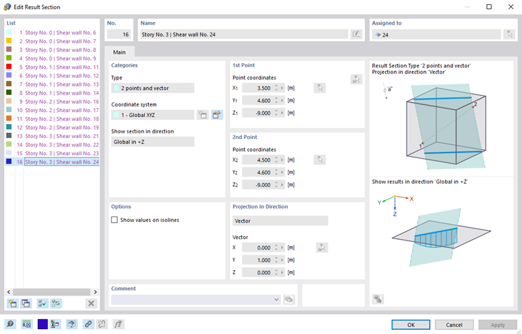
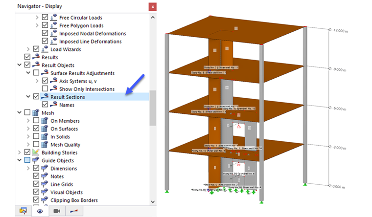
The concept of the result sections is described in the chapter Result Sections of the RFEM manual. As usual, you can show and hide the result sections in the "Navigator – Display." The options for evaluating the result sections for the individual building stories conform to the add-on properties.
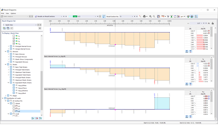
The following image shows the result diagrams of the surface moments nx, ny, and nxy, which are on the third floor for Shear Wall 13 of the example Building Model – Result Sections. In the navigator of the "Result Diagrams" window, you can also select other result types to be displayed.
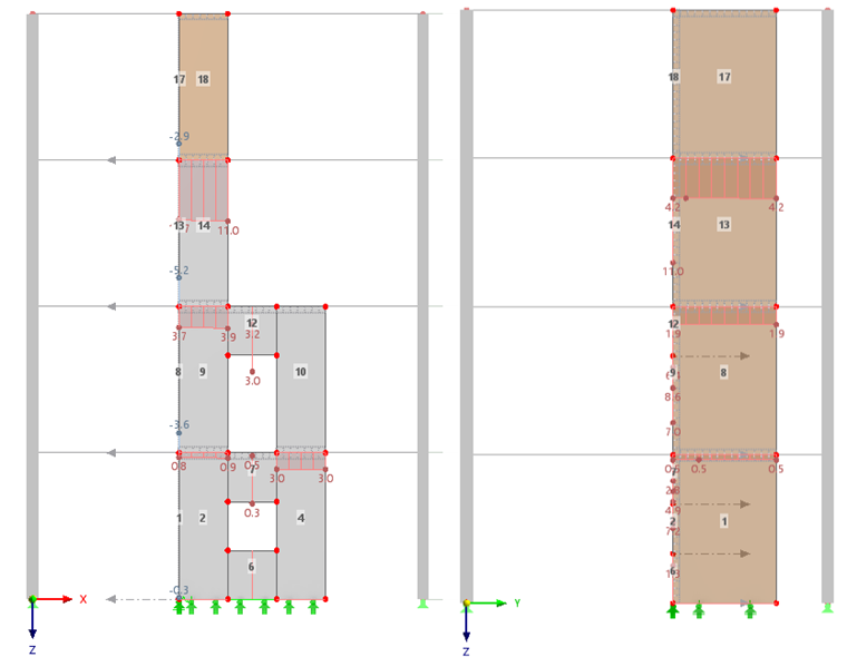
It is also possible to display the diagrams and values of a result section on the model. The following image again shows Shear Wall 13 with the axial force in ny. You can switch between the various results by switching between the categories "Global Deformations," "Surfaces," and "Distribution of Loads." In the case of the "Surfaces" category selected for the image, the result type determines whether an internal force or stress is displayed.

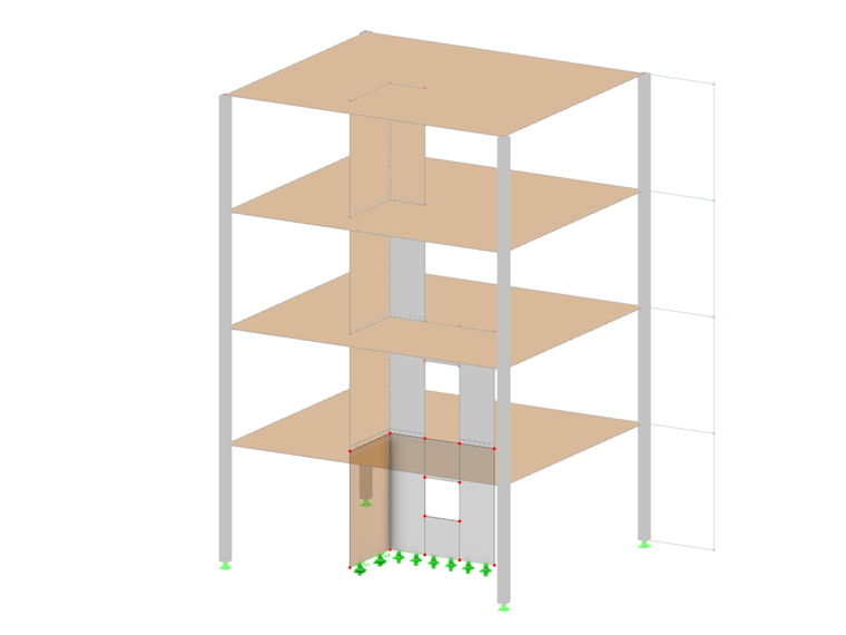
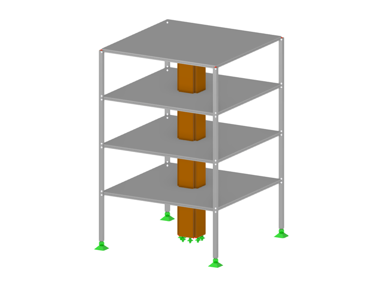
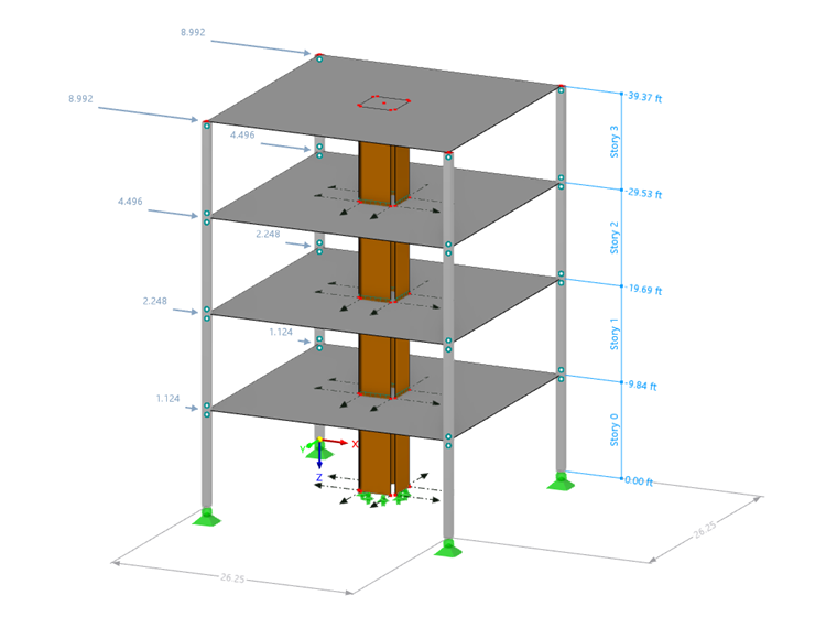
The Building example presents further results that are possible with the result sections. This building consists of four stories with the basic dimensions of 8 m × 8 m. Each story has a height of 3 m. The building is symmetric. The individual shear walls of the stiffening building core are located exactly in the center of the building. They are not connected to each other. The shear walls are supported as rigidly fixed on the ground floor.
The materials and dimensions of the structural components are as follows:
- Slabs made of reinforced concrete C20/25, d = 20 cm
- Columns made of reinforced concrete C20/25, 24/24 cm
- Stiffening building core made of cross-laminated timber with 5 layers C24, d = 20 cm, length 1 m
The cross-laminated timber wall is connected to the slabs with a release of rotation (φx = 0) using line hinges. At the outer four corner nodes of the building, there are reinforced concrete columns as hinged columns with moment hinges. This model has no story slab stiffnesses of the "rigid link" type.
The building is analyzed for two load cases. In Load Case 1, a surface load of 1 kN/m² is applied to each story. In Load Case 2, a nodal load of 5 kN, 10 kN, 20 kN, and 40 kN is applied – increasingly from the ground floor to the top floor each – in the global x-direction.
The FE mesh size is selected with 14 cm in order to obtain the lowest possible strain effects and to obtain the calculated masses and displacements quickly.
The center of gravity is exactly in the center for the X and Y direction equal to 4 m. For a targeted evaluation of the deformations, an additional node is created in each story.
In the "Navigator - Results", you can select among three basic result types (see Image Result Section on Model):
- Global Deformations
- Surfaces
- Distribution of Loads
Global Deformations can be selected as usual in the top category in the Navigator – Results.
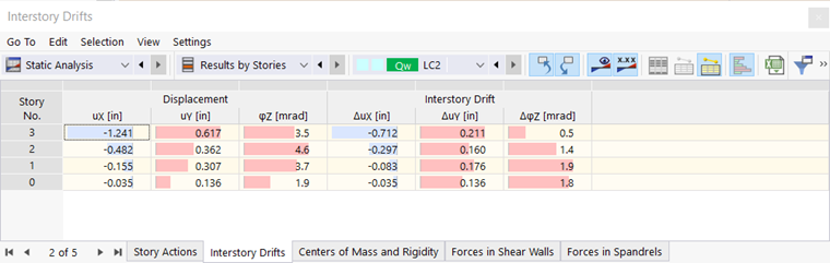
For the building, the displacement of the individual stories in Load Case 2 is of interest. The following image shows the deformations in the Y and X directions.
You can also evaluate the deformations of a story in the "Interstory Drifts" table, which is available in the "Static Analysis" category and the "Results by Story" subcategory.