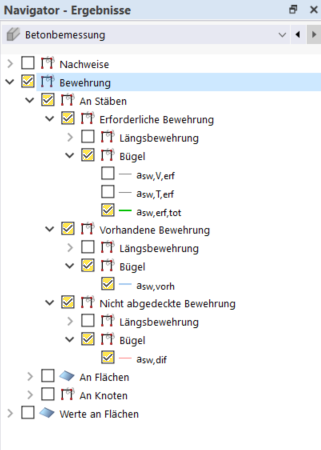
In general, you can use the "Results navigator" after the design to display the required, existing, and previously uncovered reinforcement on members, surfaces, and nodes in the graphic. Now, you should specifically analyze how the additional reinforcement can be defined in the beam and at the nodes of punching shear.
Additional Reinforcement in Member Set
By activating the corresponding display options, you can see at which points in the member set the additional stirrup reinforcement is required.
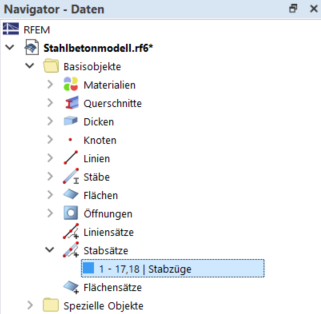
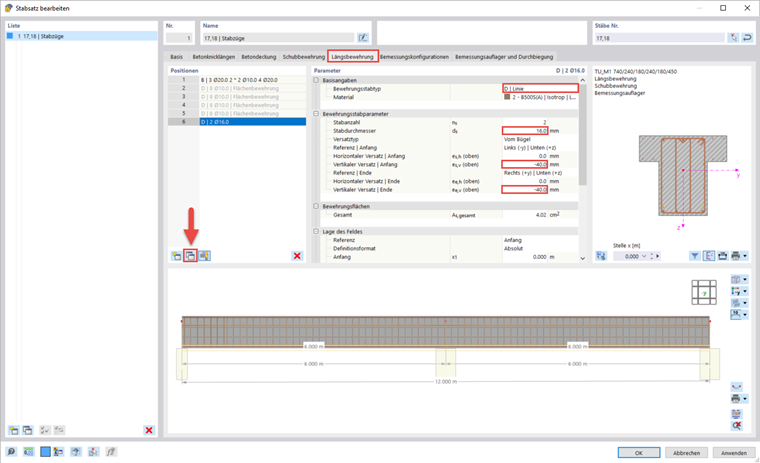
You can enter this additional reinforcement in the settings of the member set. To do this, open the editing dialog box by double-clicking the member set in the "Data navigator".
There, you can copy the previous shear reinforcement in the "Shear Reinforcement" tab using the
![]() button. The area for which it is defined is automatically divided in the middle. However, you can also define your own delimitations in the "Position of Field" section, which allows you to insert the additional reinforcement in the relevant sections only. Furthermore, you can change the stirrup type in the Base Data.
button. The area for which it is defined is automatically divided in the middle. However, you can also define your own delimitations in the "Position of Field" section, which allows you to insert the additional reinforcement in the relevant sections only. Furthermore, you can change the stirrup type in the Base Data.
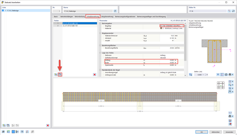
In the same way, you can define the missing longitudinal reinforcement. The various types of reinforcement members are explained in the manual. In the webinar, a smaller member diameter of 16 mm and a vertical offset of −40 mm were selected, compared to the original longitudinal reinforcement.
Punching Shear Design and Additional Surface Reinforcement
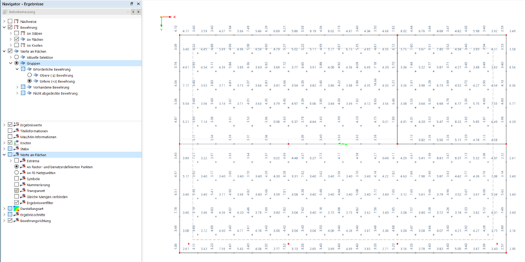
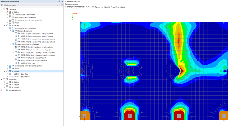
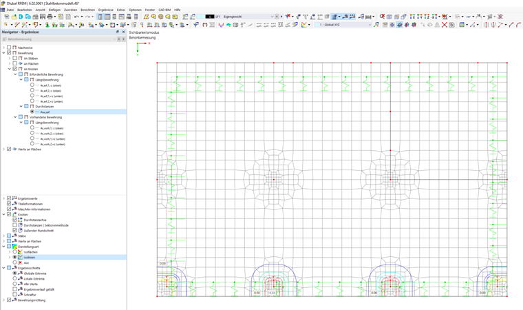
Select the ceiling slab and limit the visibility to this object in order to be able to see the results on the surface. You can also display the results of the punching shear design at the nodes in the "Results navigator".
Use the
![]() button to open the control panel. There, you can see the meaning of the colors used in the result display in the
button to open the control panel. There, you can see the meaning of the colors used in the result display in the
![]() area.
area.
Use the
![]() button to display the surface results as isobands or contour lines.
button to display the surface results as isobands or contour lines.
If you now display the punching shear reinforcement at the nodes, the result is zero, although the area around the node is overloaded. This is because the program tries to generate the required reinforcement first using the longitudinal reinforcement. Therefore, the specified required longitudinal reinforcement replaces the punching shear reinforcement.
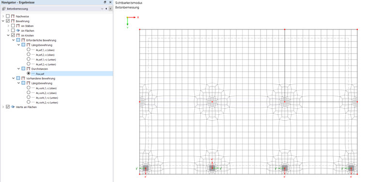
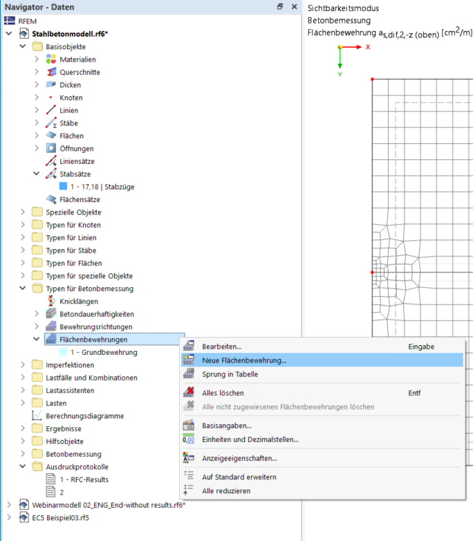
You can enter the required longitudinal reinforcement as surface reinforcement, which is created in the "Data navigator".
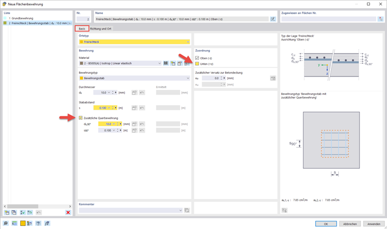
Select a free rectangle as the location type and enter the desired dimensions of the reinforcement. In the webinar, this has a member spacing of 0.1 m in the longitudinal and transverse directions.
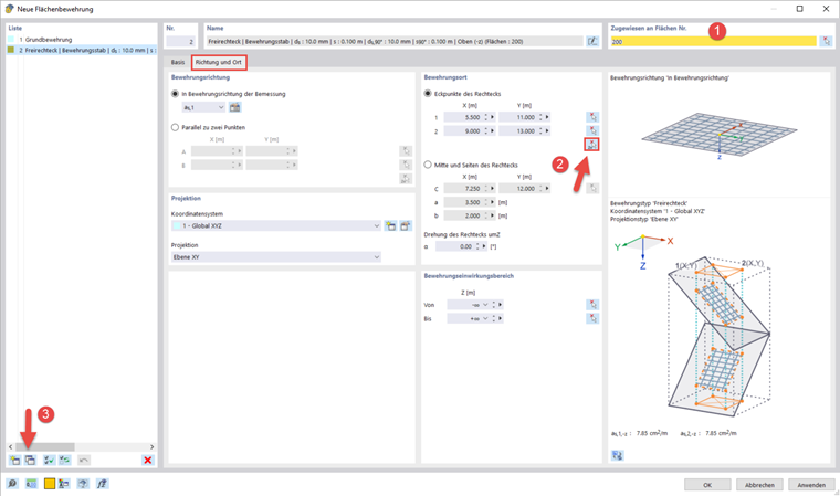
First, enter the surface where the reinforcement should be located in the "Direction and Location" tab. Then, you can use
![]() to select two points in the graphic between which the reinforcement is to be arranged in a rectangular manner. Use the
to select two points in the graphic between which the reinforcement is to be arranged in a rectangular manner. Use the
![]() button to copy the surface reinforcement and insert it at another position in the graphic.
button to copy the surface reinforcement and insert it at another position in the graphic.
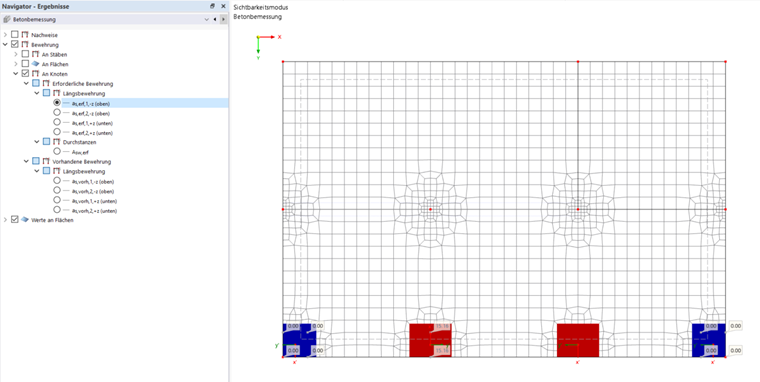
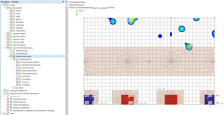
You can display the created surface reinforcement under the types for the concrete design in the "Display navigator".
It is not possible to avoid the punching shear reinforcement on the foundation plate. If you display the reinforcement as contour lines, the perimeters are displayed.
Groups
For example, you can use the groups in the "Results navigator" to display the required reinforcement in the reinforcement direction. To do this, activate the transparent display of the result values in the lower area of the navigator.