This section explains how you can enter a beam under the ceiling of the ground floor in RFEM 6.
Use the
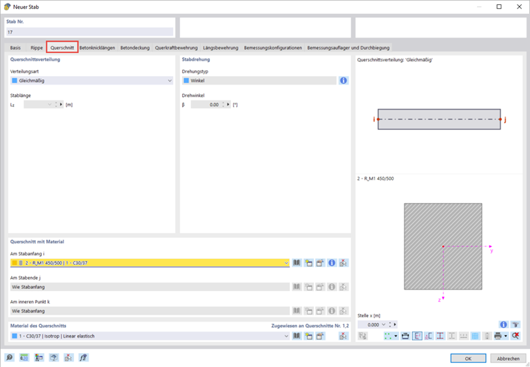
![]() button in the toolbar to create a new member. Select the Rib member type and define a rectangular cross-section with the dimensions 450 mm × 500 mm in the "Sections" tab.
button in the toolbar to create a new member. Select the Rib member type and define a rectangular cross-section with the dimensions 450 mm × 500 mm in the "Sections" tab.
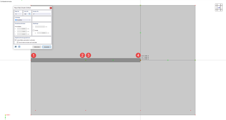
In the next step, arrange the member in the workspace. The dimensions of the flange are only edited then, since the information, such as the adjoining surface, is taken from the position of the rib member.
Click "OK" to confirm your entry and then click the edge points of the beam one by one to define two new members. Double right-click to finish the selection.
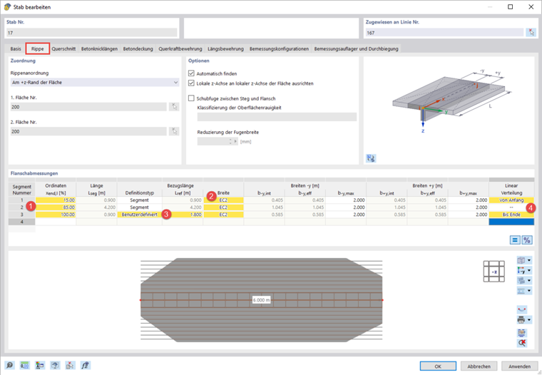
Double-click the left rib member to open the "Edit Member" dialog box and go to the "Rib" tab. The "Assignment" section has already been completed automatically.
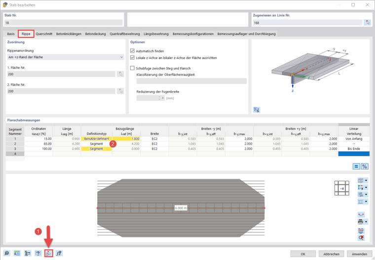
In the "Flange Dimensions" section, you can divide the flange into several segments, in contrast to RFEM 5. Define three segments that extend to 15%, 85%, and 100% of the member (1). Furthermore, specify the width determination according to Eurocode 2 (2). For the last segment, you can define a user-defined length of 1.8 m. This is necessary, as the segment length of the adjacent beam also needs to be taken into account in a continuous system. It is also possible to define a linear distribution of the effective width in the segments (4).
After opening the edit dialog box for the second rib, you can quickly enter the flange dimensions by copying the data of the first rib. To do this, you can use the
![]() button to select the first rib member (1). However, note that it is now necessary to adjust the reference length in the first segment (2).
button to select the first rib member (1). However, note that it is now necessary to adjust the reference length in the first segment (2).
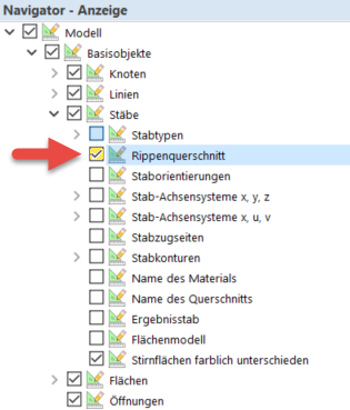
You can display the rib section in the main workspace by activating the corresponding check box in the Display navigator.