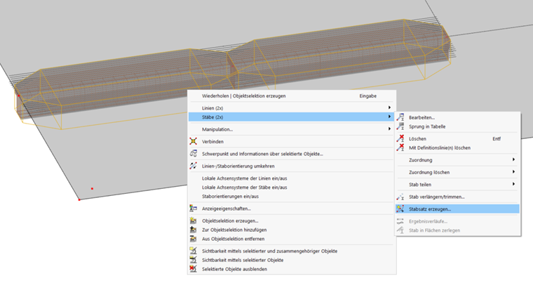
Since the beam is to be designed as a whole, the following section shows you how to connect the individual members to create a member set.
Creating Member Set
After creating a member set for the beam and activating the design properties, you can define all the specifications for the design on the member set.
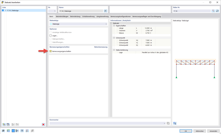
The input options for the concrete cover and the design configurations are the same as for the surfaces.
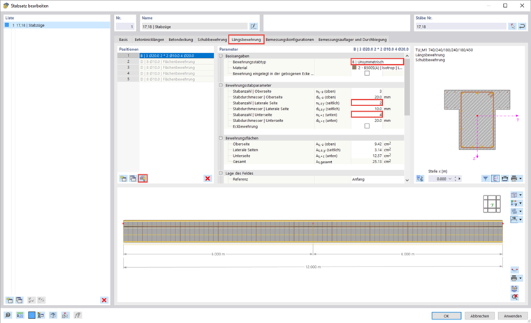
Reinforcement in Member Set
For the member set, you can define the specifications for the shear and longitudinal reinforcement separately. Especially for the longitudinal reinforcement, the surface reinforcement that runs parallel to the rib is generated directly. If this is not desired, you can deactivate the function using the
![]() button. In the webinar, an asymmetrical reinforcement distribution with two members on the top and four members on the bottom was selected. For the shear reinforcement, the distance has been changed to 0.15 m.
button. In the webinar, an asymmetrical reinforcement distribution with two members on the top and four members on the bottom was selected. For the shear reinforcement, the distance has been changed to 0.15 m.
Design Supports & Deflection
In the "Design Support and Deflection" tab, you can assign specific support conditions to the member set. Design supports affect the design checks (moment redistribution, moment reduction, shear force reduction) and the reinforcement (anchorage length). Furthermore, you can enter the specifications for the deflection analysis here.
Create a new design support using the
![]() button (1). Then, assign it to the start and end of the member set as well as the intermediate nodes (2 & 3). Furthermore, specify the direction for the deflection analysis in this dialog box.
button (1). Then, assign it to the start and end of the member set as well as the intermediate nodes (2 & 3). Furthermore, specify the direction for the deflection analysis in this dialog box.
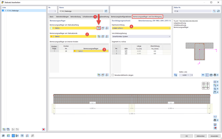
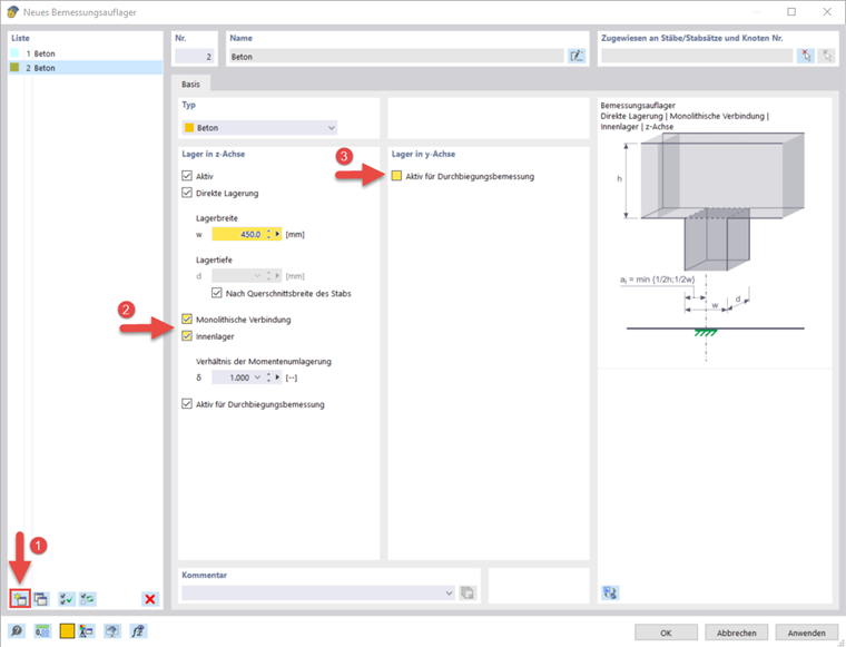
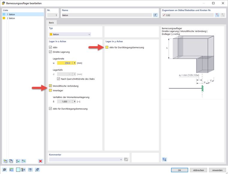
In the "New Design Support" dialog box, you can specify the settings of the support type. For the end support at the start of the member set, enter a support width of 250 mm and a monolithic connection to the wall. The support width refers to the longitudinal axis x of the member. The "support depth" d results from the cross-section width of the member by default. Deactivate the inner support, for which other conditions would apply, in order to determine the design moments and anchorage lengths. It is also possible to specify whether the design supports should also be used as a segmentation for the deflection analysis.
For the design support at the intermediate node and at the end of the member set, a support width of 450 mm was selected and the inner support option was activated in the webinar.