To define a new member, click the
![]() button in the toolbar. The "New Member" dialog box appears where you can see the cross-section already set for the chords.
button in the toolbar. The "New Member" dialog box appears where you can see the cross-section already set for the chords.
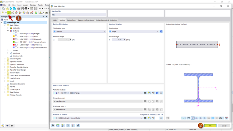
After you confirming your entry by clicking "OK", you can define the start and end points of the member. The bottom chord should go from the origin to [X: 20 m / Y: 0 m / Z: 0 m]. Click the points one by one and then right-click the entry to finish it.
Dividing Members
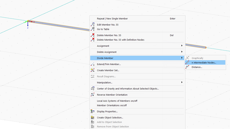
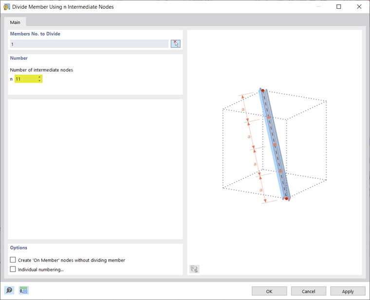
Since the posts will divide the bottom chord into 12 sections, you need 11 intermediate nodes where the posts begin. Right-click the member to open the "Divide Member Using n Intermediate Nodes" dialog box.
Copying Members
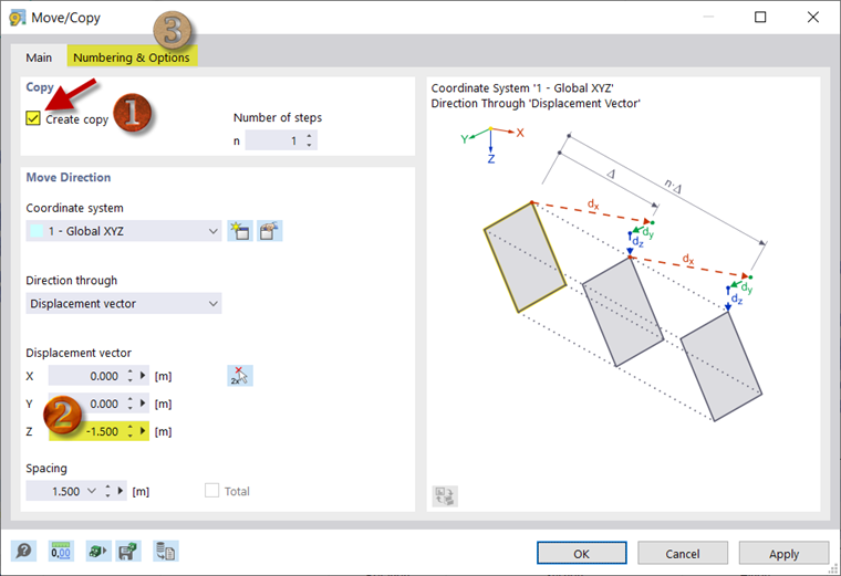
To create the top chord, you can copy the bottom chord using the
![]() button and move the copy upwards. To do this, activate the "Create Copy" option in the dialog box and specify the chord to be copied upwards by 1.5 m.
button and move the copy upwards. To do this, activate the "Create Copy" option in the dialog box and specify the chord to be copied upwards by 1.5 m.
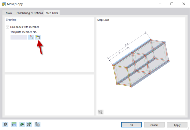
Then, activate the step link in the "Numbering and Options" tab. This allows you to connect the nodes of the top and bottom chords directly to the posts. After selecting "Link nodes with member" in the "Step Links" tab, use the
![]() button to define the cross-section of the posts.
button to define the cross-section of the posts.

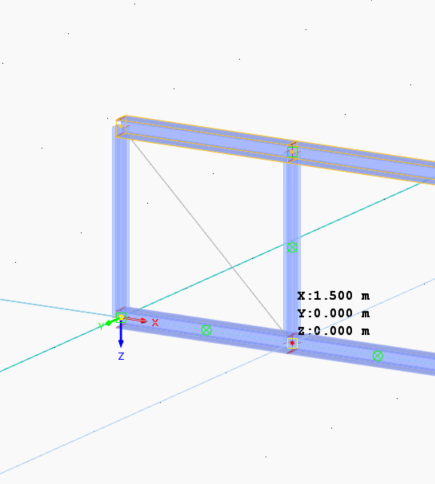
Select the truss "Member Type" for the posts. For this type, a hinged support is set by default. In the Section tab, you can select the relevant cross-section (HEA 100). After clicking "OK" twice to confirm it, the top chord and posts are generated automatically.
Mirroring Members
For the diagonals, use
![]() to create a new truss member with the corresponding cross-section. This should be directed from [X: 0 m / Y: 0 m / Z: -1.5 m] towards [X: 1.5 m / Y: 0 m / Z: 0 m].
to create a new truss member with the corresponding cross-section. This should be directed from [X: 0 m / Y: 0 m / Z: -1.5 m] towards [X: 1.5 m / Y: 0 m / Z: 0 m].
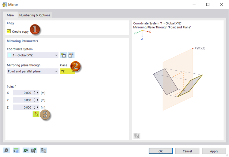
You can copy the member you have just created by selecting it while holding down the Ctrl key and dragging it to the right. Create the first six diagonal members in this way. The other six diagonal members are to be created by mirroring. To do this, select all six diagonal members that have already been created and click
![]() to open the "Mirror" dialog box. Activate the "Create Copy" option, set the YZ plane as the mirror plane, and select a point on the mirror axis (3). This point can be one of the two nodes in the middle of the truss bridge. After the confirmation, the remaining diagonal members are created.
to open the "Mirror" dialog box. Activate the "Create Copy" option, set the YZ plane as the mirror plane, and select a point on the mirror axis (3). This point can be one of the two nodes in the middle of the truss bridge. After the confirmation, the remaining diagonal members are created.
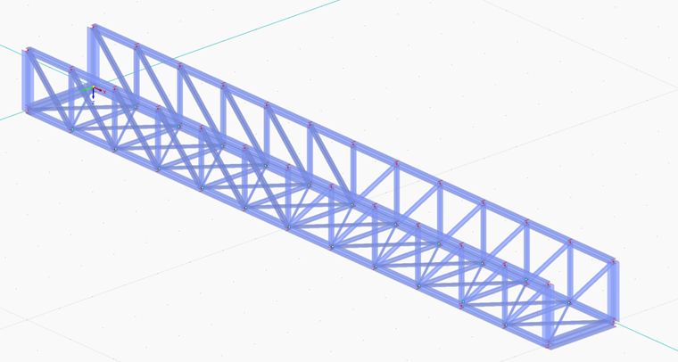
Select the structure you have modeled so far and copy it by 2 m in the X‑direction.
Defining Joints
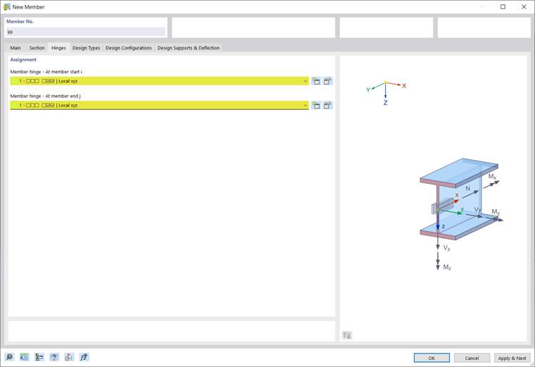
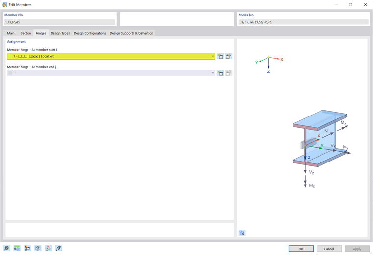
For the transverse beams, create a new member of the "Beam" type and select the "Hinges" option. Then, define the corresponding cross-section in the "Section" tab. In this case, the joints are selected manually in the "Joints" tab. Use the
![]() button to create a new member hinge. Neither the member hinge at the member start nor the one at the member end should transfer any bending moments. For this reason, the rotation directions φy and φz are selected in the "Hinge Conditions" sections and thus blocked.
button to create a new member hinge. Neither the member hinge at the member start nor the one at the member end should transfer any bending moments. For this reason, the rotation directions φy and φz are selected in the "Hinge Conditions" sections and thus blocked.
Insert a member between two opposite nodes of the bottom chords, then copy it.
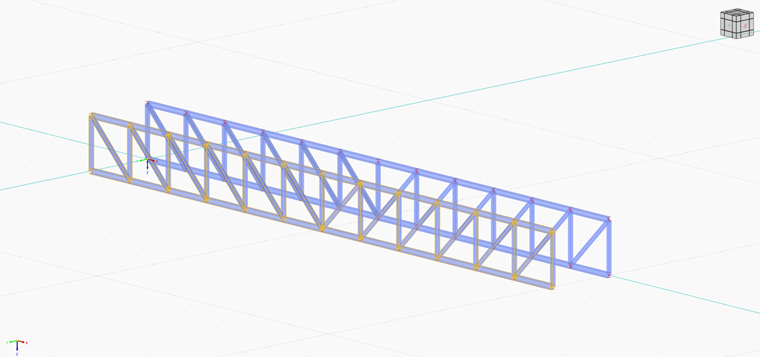
For the transverse frames, create a member of the "Beam" type with the relevant cross-section. This should be added at both ends of the bridge.

Editing Members
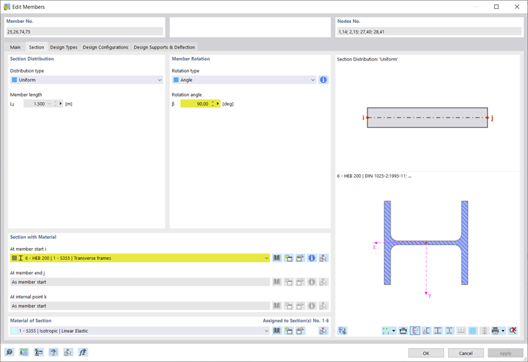
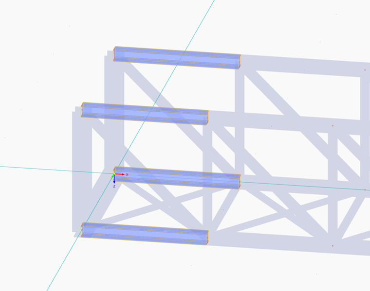
Outer posts are also part of the transverse frame, which is why it is necessary to change the material here. To do this, select all four outer posts and double-click to open the "Edit Members" dialog box.
In the "Section" tab, select Cross-Section for Transverse Frame (HEB 200), and change the rotation angle to 90° in the "Member Rotation" dialog box section. This will align the posts properly.
Since the chords have the "Beam" member type, they have been rigidly connected to the transverse frame so far. You can change this to a hinged connection by selecting the outer members of the chords and adding a hinge at the member start. On the other side of the truss bridge, a hinge should be inserted at the member end.
Multiple Copying of Members
The last structural element is the crossing. These can only absorb tensile forces. Therefore, select the "Tension" "Member Type". Also, define the corresponding cross-section again. Insert both crossings in the first bridge section.
Select both crossings and use the
![]() button to open the "Move/Copy" dialog box. To copy the crossings directly into all other bridge sections, select the "Create Copy" option with a number of 11 steps.
button to open the "Move/Copy" dialog box. To copy the crossings directly into all other bridge sections, select the "Create Copy" option with a number of 11 steps.
The displacement vector is [X: 1.5 m / Y: 0 m / Z: 0 m].