


For the stability design according to the equivalent member method, it is necessary to define the effective lengths in order to determine a critical load for the stability failure. You can select whether you want to define the effective length coefficients and nodal supports manually, or import the effective lengths already calculated in the stability analysis.
Import of Effective Lengths from Stability Analysis
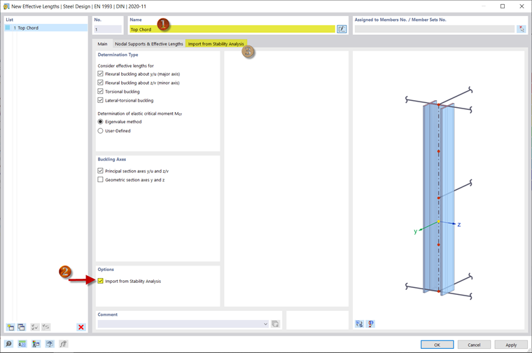
You can create new effective lengths under "Types for Steel Design" - "Buckling Lengths" in the navigator. Define the effective length name and activate the "Import from Stability Analysis" option.
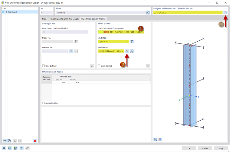
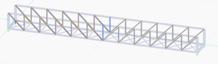
To import the effective lengths from the stability analysis, open the corresponding tab. For each principal axis, you can define the mode shape of a specific load case. In the example of the truss bridge, only the buckling "About Axis z/v" is considered. There you select the governing load combination for the critical load factor, Load Combination 9 in this case, and select one of the two middle members of the right upper chord (2) using
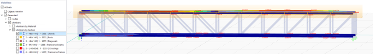
![]() . Since these members have the highest load, their effective length can be assumed for all members of the upper chords. Assign the effective length to the members (3) by limiting the visibility to the chords and drawing a window over both top chords.
. Since these members have the highest load, their effective length can be assumed for all members of the upper chords. Assign the effective length to the members (3) by limiting the visibility to the chords and drawing a window over both top chords.
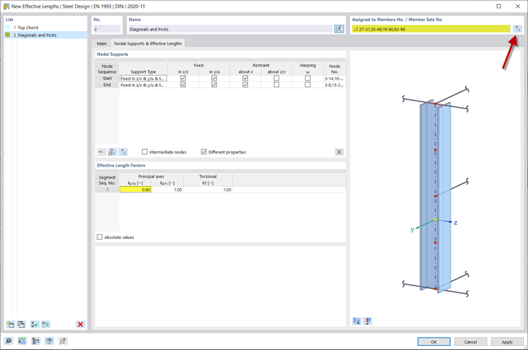
Manual Definition of Effective Lengths
In the "Nodal Supports and Effective Lengths" tab, you can define your own effective length coefficients and supports. For example, create a new effective length for the diagonals and posts and enter the effective length coefficient ky/u = 0.9 manually. Then, assign the effective length to the corresponding members.
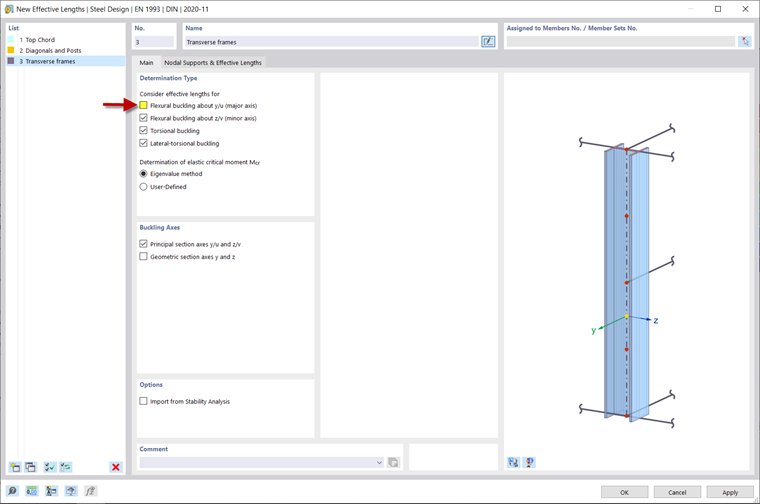
Stability Failure Modes to Be Checked
You can specify which forms of stability failure are to be checked in the "Main" tab. Create a new effective length for the transverse frames and deactivate the flexural buckling about the principal axis, for example. No stability analysis is thus carried out for this deformation direction. Furthermore, deactivate the restraint at the top of the members, as the transverse frames are the stabilizing elements of the steel bridge and are not in the plane themselves.
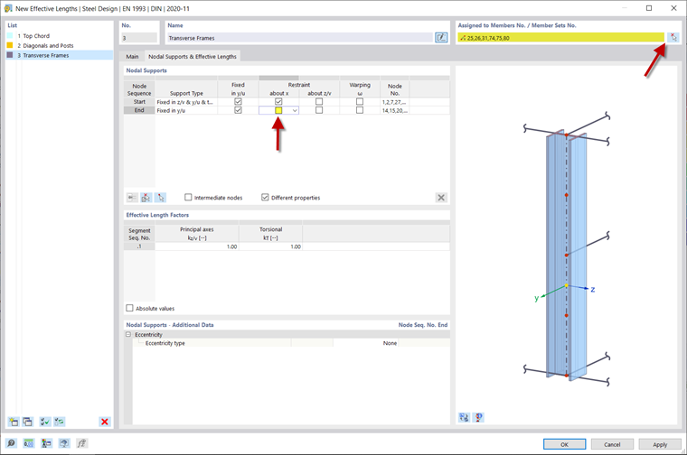
Assign this effective length to the outer posts and both posts in the middle of the bridge.